500 Volt Megger & Polarization Index Test on Generator Rotors
Introduction
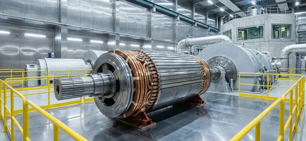
The rotor (field) winding of a large utility generator operates at relatively low DC excitation voltages—typically 100–500 V—yet must remain highly reliable under centrifugal forces, thermal cycling, and vibration. The 500 Volt Megger Test (insulation resistance or IR test) combined with the Polarization Index (P.I.) calculation is a simple, non-destructive, offline diagnostic used to assess the dielectric condition of the rotor winding insulation.
Performed with a 500 V DC megohmmeter (commonly called a “Megger”), the test quickly detects moisture, contamination, aging, or physical damage that could lead to ground faults or turn-to-turn shorts.
Terminology clarification: “Megger Test” is industry shorthand for insulation resistance testing using a megohmmeter. The Polarization Index (P.I.) is derived from the same test by taking the ratio of the 10-minute IR reading to the 1-minute IR reading.
Because rotor windings operate at much lower voltages than stator windings, they are held to a lower insulation standard; a lower P.I. is often observed and accepted on rotors.
Background
Rotor insulation failures can cause sudden loss of excitation, pole slipping, or catastrophic ground faults that trip the generator offline. Early rotor insulation problems were often discovered only after a fault occurred. The 500 V Megger test became a standard utility practice in the 1950s–1960s because it is fast, portable, and sensitive to moisture and contamination—common rotor issues due to hydrogen-seal oil leaks, condensation during outages, or carbon dust from brushes. The P.I. was added later to help distinguish between reversible moisture/contamination (which lowers P.I.) and permanent insulation degradation.
Today the test is performed during commissioning, routine outages, post-repair verification, and as part of root-cause investigations on all large synchronous generators.
Theory of Operation
The rotor winding insulation behaves electrically as a complex dielectric with both capacitive and resistive components. When a steady DC voltage (500 V) is applied, the total current consists of three components:
- Capacitive charging current (decays quickly)
- Absorption (polarization) current (decays slowly)
- Leakage (conduction) current (steady-state)
The megohmmeter measures the apparent insulation resistance (IR) as voltage divided by the remaining current after the initial surge. The Polarization Index is defined as:
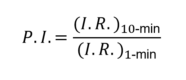
A high P.I. (>2.0) indicates that absorption current has decayed and leakage current dominates—typical of dry, clean insulation. A low P.I. indicates persistent absorption or leakage current caused by moisture or contaminants.
Why Rotors Show Lower P.I. Values
Rotor windings operate at much lower voltages (typically <500 V DC) than stator windings (nominally 4–26 kV AC). The electric stress across the rotor insulation is therefore far lower, so the insulation system can tolerate more surface contamination or minor moisture without risk of tracking or breakdown. In addition, rotor insulation is often exposed to brush carbon dust, hydrogen gas, and seal-oil vapors, which naturally depress P.I. readings. Industry standards therefore accept lower P.I. thresholds for rotors than for stators, recognizing that the risk of failure is inherently lower at excitation voltages.
Need Expert
Engineering Guidance?
Get independent technical advisory for your power generation project, from design review to project oversight.
Test Procedure Overview
The test is performed offline with the rotor in place (field leads disconnected and grounded) or removed, depending on outage scope. Key steps include:
- Preparation: Isolate the rotor field leads, ground the shaft, and ensure the rotor is at ambient temperature. Clean slip rings and brush holders if accessible. Use a calibrated 500 V DC Megger. If the unit has brushless excitation, you must either isolate the (+) and (–) leads entirely from the diode wheel, or if the diode wheel is included in the test then you must place a jump across the diodes to prevent over-voltaging them in the reverse bias direction.
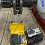
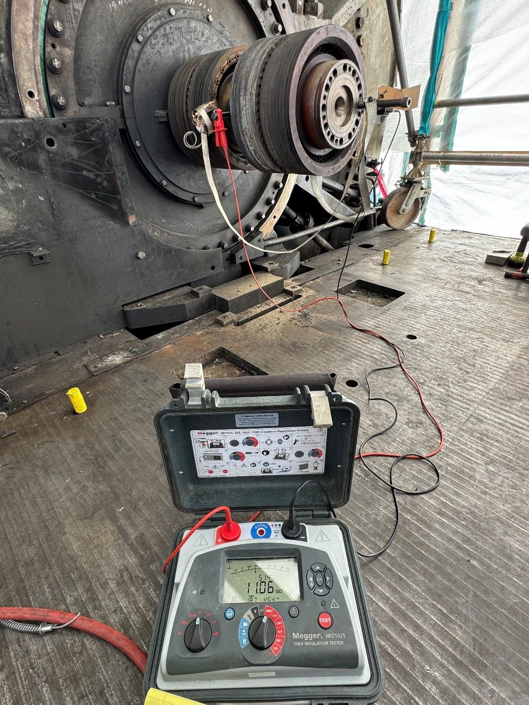
- Test Setup: Connect the Megger positive lead to one field terminal and the negative lead (ground) to the rotor shaft. Ensure danger tape is up, and inform all other workers to remain clear.
- Measurement: Apply 500 V DC and record the 1-minute IR value, and continue to record the insulation resistance every minute. Continue the test and record the 10-minute IR value.
- P.I. Calculation: Compute P.I. = IR₁₀ₘᵢₙ / IR₁ₘᵢₙ.
- Safety: Discharge the winding through a resistor after testing and verify zero voltage before touching leads. It is a good practice to leave the rotor winding grounded to the shaft after testing is complete.
The entire test typically takes less than 15 minutes per rotor.
Interpreting Results
Results are evaluated against temperature-corrected values (usually normalized to 25 °C) and OEM baselines.
- Insulation Resistance (IR): Minimum acceptable 1-minute IR is typically ≥1 MΩ per kV of rated field voltage (or simply ≥1 MΩ for most rotors at 500 V test voltage). Values below 0.5 MΩ are considered poor. Ideally, readings should be well over 100 megohms.
- Polarization Index (P.I.):
- >2.0 = excellent (dry and clean)
- 1.5–2.0 = acceptable for rotors
- 1.0–1.5 = marginal; investigate moisture or contamination
- <1.0 = unacceptable (wet or severely contaminated)
Because rotors operate at much lower voltages, a P.I. as low as 1.25 is often acceptable, whereas stator windings normally require P.I. >2.0 (or >3.0 for critical units). Trending is essential: a declining P.I. or IR over successive outages signals progressive degradation even if absolute values remain marginally acceptable.
Repair Scenarios
If results are unacceptable:
- Minor Issues (low P.I. due to surface moisture or light contamination): Perform a controlled dry-out (heaters and/or dehumidifiers) followed by re-testing. Clean slip ring insulation and brush holders.
- Moderate Issues (persistent low IR/P.I. after drying): Inspect and clean rotor winding surfaces, replace worn slot liners or inter-turn insulation where accessible, or apply insulating varnish.
- Severe Issues (IR <0.5 MΩ or P.I. <1.0 even after drying): Localized coil repair, full rotor rewind, or replacement of damaged pole coils. A retaining-rings-off inspection and cleaning may be warranted. Full or partial rotor rewind may be indicated in the most severe circumstances.
All repairs must be followed by a successful 500 V Megger/P.I. test before the rotor is returned to service.
IEEE & ANSI Documentation
The primary reference is IEEE Std 43-2013, IEEE Recommended Practice for Testing Insulation Resistance of Electric Machinery, which details the 500 V Megger test procedure, temperature correction, and P.I. interpretation for both stator and rotor windings. Additional guidance for synchronous-machine rotors appears in IEEE Std 56-2016, IEEE Guide for Insulation Maintenance of Electric Machines, and IEEE Std 115-2019, IEEE Guide for Test Procedures for Synchronous Machines. IEEE 43 explicitly notes that rotor windings, because of their lower operating voltage, may be held to lower P.I. and IR acceptance criteria than stator windings. The standards are frequently dual-designated as ANSI/IEEE and represent the globally recognized best practice.
Summary & Conclusions
The 500 Volt Megger & P.I. test is a fast, low-risk, and highly informative offline diagnostic for assessing the insulation condition of large utility generator rotors. By measuring insulation resistance and calculating the Polarization Index, technicians can detect moisture, contamination, and aging long before a ground fault occurs. Because rotor windings operate at much lower voltages than stator windings, they are held to a correspondingly lower standard—lower P.I. values are routinely accepted without compromising reliability.
When performed per IEEE Std 43 and interpreted with temperature-corrected baselines, the test enables proactive dry-out or repair decisions that prevent forced outages and extend rotor life. As generator fleets age and operate under increasing cyclic duty, routine 500 V Megger/P.I. testing remains a cornerstone of modern predictive maintenance programs, delivering high value at minimal cost.

About the Author
Charles J. Wolfe is the Founder and Principal Engineer of Generex Consulting, with over 30 years of global experience in power generation. He is a recognized expert in generator and excitation systems, trusted by clients worldwide for solving complex engineering challenges.