Generator Rotor Balancing, Shaft Alignment & Run-Out Guide
Introduction
Rotor balancing, shaft alignment, and mechanical run-out procedures are fundamental to the mechanical reliability and smooth operation of large utility turbine-driven generators. Excessive vibration from imbalance, misalignment, or excessive run-out can lead to premature bearing wear, fatigue cracking, increased noise, and reduced efficiency, ultimately resulting in forced outages or major component damage. These procedures ensure the rotor operates within tight tolerances under high-speed, high-load conditions. For consulting firms specializing in generator testing, inspection, and repair, mastery of these techniques allows precise diagnostics, targeted corrections, and verification that minimize downtime and extend equipment life. This article provides a practical overview of the principles, methods, and best practices for achieving and maintaining optimal rotor dynamics in utility-scale machines.
Background
Large turbine-driven generators feature heavy rotors (often weighing tens of tons) operating at 3600 or 1800 rpm in a demanding environment of thermal cycling, electromagnetic forces, and continuous vibration. Even small imbalances or misalignments amplify centrifugal forces and can cause resonance issues or bearing overload. Mechanical run-out—deviation from a perfect cylindrical surface—further complicates vibration readings and can mask or mimic true mechanical problems. Industry experience shows that improper balancing or alignment during installation or after repairs is a leading contributor to vibration-related outages. Modern predictive maintenance programs rely heavily on accurate balancing, alignment, and run-out data to establish baselines and detect changes over time. Proper execution of these procedures is especially critical during major outages when rotors are removed and reinstalled.
Principles of Operation
Rotor balancing corrects mass distribution so the center of mass coincides with the geometric axis of rotation, minimizing centrifugal forces at operating speed. Imbalance produces a once-per-revolution (1X) vibration vector whose amplitude increases with the square of rotational speed. Balancing is performed in two planes (static and dynamic), or in multiple planes for flexible rotors. Low-speed balancing occurs on a balancing machine, while high-speed balancing (at or near operating speed) accounts for rotor bow and modal behavior.
Shaft alignment ensures that the centerlines of the turbine rotor, coupling, and generator rotor form a continuous, straight axis under operating conditions (hot alignment). Misalignment generates high 1X and 2X vibration with strong axial components and phase differences across couplings. It also induces cyclic loading on bearings and couplings. Thermal growth, foundation settling, and soft-foot conditions must be considered for cold-to-hot alignment targets.
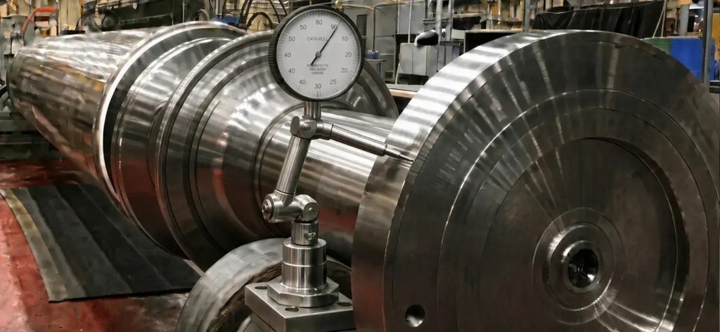
Mechanical run-out measures the total indicated run-out (TIR) of the shaft journal or coupling surfaces using dial indicators or proximity probes. It includes mechanical (geometric) run-out from machining tolerances, bow, or handling damage, and electrical run-out from material inhomogeneities affecting eddy-current sensors. Excessive run-out distorts vibration signals and can cause false alarms or inaccurate balancing. Acceptable limits are typically very tight (e.g., <0.001–0.002 inches TIR, depending on diameter and speed).
Balancing Procedures
These procedures are performed with the rotor removed or during slow-roll / turning-gear conditions:
- Preparation — Clean journals and coupling faces; verify rotor support on stable pedestals or a balancing machine; install calibrated sensors.
- Mechanical Run-Out Measurement — Mount dial indicators or proximity probes at multiple axial locations (journals, coupling). Rotate the rotor slowly (or at low speed) and record peak-to-peak TIR in multiple planes. Separate mechanical and electrical run-out where possible.
- Rotor Balancing — Perform low-speed two-plane or multi-plane balancing using trial weights and influence coefficients. For flexible rotors, conduct high-speed balancing in a vacuum chamber or on-site if facilities allow. Verify that residual imbalance meets ISO 1940 or API tolerances.
- Shaft Alignment — Use laser alignment systems for high precision across the turbine-generator train. Measure cold alignment, account for thermal growth offsets, and perform hot alignment verification after startup. Check for soft foot and pipe strain.
- Verification and Documentation — Record all data with phase angles, vibration spectra, and before/after comparisons. Trend run-out and vibration levels across outages.
Procedures are typically executed during major outages (every 4–8 years) or after rotor removal for winding or bearing work, with laser tools enabling faster, more accurate field alignment.
Place a Generex Technical Field Advisor on-site to oversee work, guide technicians, and protect your interests.
Need Maintenance Direction
and Support?
Rebalancing Scenarios
Repair scope depends on the measured conditions:
- Minor — Small residual imbalance or minor run-out: add balance weights or perform in-situ field balancing during a short outage (1–3 days).
- Moderate — Excessive run-out or misalignment: machine journals lightly, install sleeves, or correct soft foot and realign the train (1–2 weeks).
- Major — Significant rotor bow, severe imbalance, or coupling damage: perform rotor straightening (thermal or mechanical methods), high-speed shop balancing, or full rotor refurbishment with a new coupling (4–12+ weeks). In extreme cases, rotor replacement may be required.
Post-repair activities always include repeat run-out checks, balancing verification, and loaded vibration acceptance testing to confirm acceptable levels.
Common Issues and Remedies
Common problems include:
- Residual imbalance — Often from uneven winding settling, material loss, or thermal bow. Remedy: precision multi-plane balancing with accurate influence coefficients.
- Misalignment — Caused by foundation settling, thermal growth errors, or improper reassembly. Remedy: laser alignment with proper cold/hot targets and soft-foot correction.
- Excessive mechanical run-out — Due to rotor bow, journal eccentricity, or handling damage. Remedy: straighten the rotor (if feasible) or machine journals to restore geometry.
- Electrical run-out interference — Affects proximity-probe readings. Remedy: map and compensate during balancing, or use mechanical indicators for verification.
- Coupling-related issues — Angular or parallel misalignment amplifying vibration. Remedy: precision laser alignment and coupling inspection/replacement.
Root-cause analysis should correlate run-out data with vibration spectra and operating history to distinguish geometric issues from dynamic problems.
IEEE and ANSI Documentation
IEEE Std 67 (Guide for Operation and Maintenance of Turbine-Generators) provides practical recommendations for rotor balancing, alignment, and run-out measurements as part of overall mechanical maintenance. It emphasizes accurate alignment during installation and after repairs to minimize vibration. Supporting references include ISO 1940 (Mechanical Vibration — Balance Quality Requirements) for balancing tolerances and API 670 (Machinery Protection Systems) for vibration monitoring that relies on clean run-out data. ANSI/IEEE C50.13 (Standard for Cylindrical-Rotor Synchronous Generators) addresses mechanical design aspects that influence balancing and alignment requirements. Thorough documentation of run-out readings, balance reports, alignment data (cold/hot), and post-repair vibration results is essential for trending, root-cause analysis, and regulatory compliance.
Summary and Conclusions
Rotor balancing, shaft alignment, and mechanical run-out procedures are critical mechanical disciplines that directly influence the vibration signature, bearing life, and overall reliability of large utility turbine-driven generators. Precise balancing eliminates unnecessary centrifugal forces, accurate alignment prevents harmful cyclic loading, and controlled run-out ensures reliable vibration monitoring and data interpretation. When performed correctly during outages or after rotor work, these procedures minimize vibration, reduce wear, and support longer intervals between major maintenance events. Common issues such as residual imbalance, misalignment, and excessive run-out can be effectively addressed through modern laser alignment tools, multi-plane balancing techniques, and careful geometric verification. Adherence to IEEE Std 67, ISO balancing standards, and API guidelines, combined with meticulous documentation and trending, ensures consistent results and regulatory compliance. For utilities operating aging or cycling fleets, expert consulting in rotor balancing, alignment, and run-out procedures delivers significant value by preventing vibration-related failures, optimizing outage scopes, and extending the service life of expensive rotor assemblies. Implementing rigorous programs in these areas is a proven strategy for achieving low-vibration, high-availability operation in today’s demanding power generation environment.

About the Author
Charles J. Wolfe is the Founder and Principal Engineer of Generex Consulting, with over 30 years of global experience in power generation. He is a recognized expert in generator and excitation systems, trusted by clients worldwide for solving complex engineering challenges.