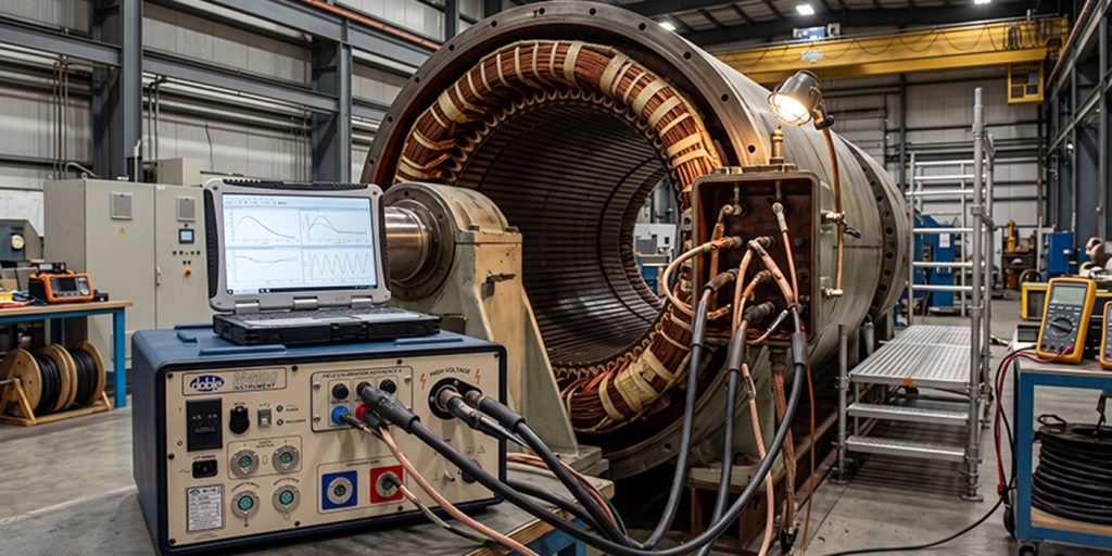
Doble Power Factor & Tan Delta Testing of Generator Stators
Introduction
Large utility generators rely on high-voltage stator windings whose insulation systems must withstand intense electrical, thermal, mechanical, chemical, and environmental stresses for decades. Degradation of this insulation—due to voids, delamination, moisture, contamination, partial discharge (PD), or aging—can lead to costly failures, forced outages, and catastrophic damage.
The Doble Power Factor test (also called the Power Factor test, Tip-Up test, or Tangent Delta / Tan Delta test) is a proven, non-destructive, off-line AC diagnostic method used to evaluate the dielectric condition of stator winding insulation. To clarify the terminology: “Doble test” is industry shorthand for power factor testing performed with Doble Engineering Company instruments (the most widely used test sets). The terms Power Factor (PF) test, Dissipation Factor (DF) test, Tan Delta (tan δ) test, and Tip-Up test all refer to the same family of measurements. The core measurement is dielectric loss; the Tip-Up variant specifically examines how PF/tan δ changes with increasing test voltage, revealing voltage-dependent defects such as voids and PD. These terms are used interchangeably in practice and in the literature.
Background
Power factor testing has been a standard diagnostic tool for rotating machinery since the mid-20th century. It provides a quantitative, repeatable assessment of insulation quality that insulation-resistance (IR) or hipot tests alone cannot deliver. Performed during factory acceptance, commissioning, routine outages, and post-repair verification, the test detects early-stage problems before they progress to PD, tracking, or breakdown. Unlike high-voltage hipot or surge tests, it is low-risk and does not stress the insulation beyond line-to-ground service levels.
Modern Doble instruments (M4100, M7100, etc.) make testing fast, automated, and highly accurate, allowing utilities to trend insulation condition over the generator’s life and schedule repairs proactively.
Theory of Operation
The stator winding insulation behaves electrically as a parallel combination of capacitance (C) and resistance (R). When an AC voltage is applied, the total current consists of two components:
- A large capacitive (charging) current IC that leads the voltage by 90° (reactive, lossless).
- A small resistive (loss) current IR that is in phase with the voltage (caused by leakage, conduction, and dielectric losses).
The vector relationship is shown in the diagram below:
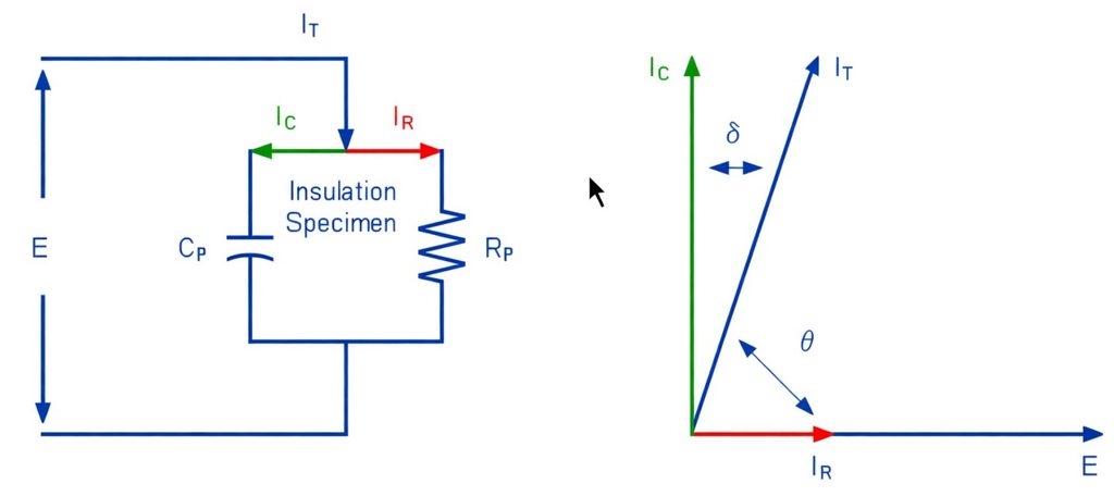
In the vector diagram:
- E is the applied test voltage (reference phasor along the real axis).
- IT is the total measured current (slightly lagging E).
- IC is the quadrature (reactive) component.
- IR is the in-phase (loss) component.
The Power Factor (PF) is defined as:
PF = cos θ = P / (E · IT) = IR / IT
where θ is the phase angle between voltage and total current, and P is the real power (the watts of loss).
tan δ = IR / IC ≈ PF (for small δ)
where δ = 90° − θ
Capacitance is also measured:
C = IC / (2πfV)
with f = test frequency, usually 60 Hz or 50 Hz. As the test voltage is increased, any voids or delaminations ionize, producing additional PD that increases IR, and therefore PF/tan δ. This voltage-dependent rise is the Tip-Up (ΔPF or Δtan δ), typically calculated as:
Tip-Up = PF100% − PF25%
Percentages are of rated line-to-ground voltage. A healthy, well-impregnated insulation system typically exhibits minimal Tip-Up; excessive Tip-Up usually signals voids, poor semiconductive coatings, or PD activity.
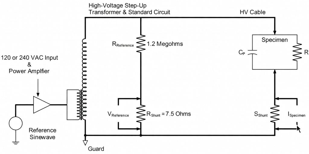
Test Procedure
The test is performed off-line with the rotor removed (or in place if air-gap clearance and safety allow). The key steps are:
- Preparation: Isolate the stator windings (neutral disconnected, phases separated). Clean accessible surfaces. For water-cooled machines, it is best to blow down and vacuum-dry the windings with a HIT skid or equivalent, but at a minimum circulate demineralized water (<0.25 μS/cm conductivity) and correct for DC losses if required.
- Test Setup: Connect the Doble test set using Guarded Specimen Test (GST) or Ungrounded Specimen Test (UST) modes. GST-GND measures slot insulation; UST emphasizes end-winding insulation.
- Voltage Steps: Apply AC voltage in steps (typically 25%, 50%, 75%, 100%, and sometimes 125% of rated line-to-ground voltage). Record watts, current, capacitance, PF, and tan δ at each step. The line-to-ground voltage is computed as the nameplate rated line voltage divided by 1.73 (the square root of 3).
- Measurements: Test each phase individually to ground and between phases. Use a resonating inductor for large machines to extend the current range. The resonating inductor shall be tuned so that its inductive reactance is equal in magnitude to the capacitive reactance of the stator winding.
- Safety: Follow IEEE safety practices; demagnetize and discharge the windings after testing.
The entire process for a large generator is typically completed in one half-shift or less.
Place a Generex Technical Field Advisor on-site to oversee work, guide technicians, and protect your interests.
Need Maintenance Direction
and Support?
Interpreting Results
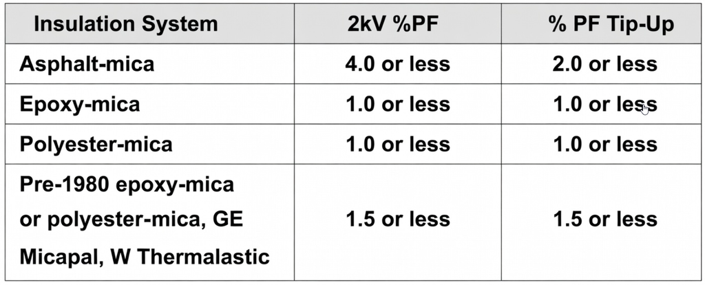
Results are evaluated against manufacturer baselines, previous tests, and industry guidelines (IEEE 286):
- Low-voltage PF / tan δ (e.g., at 25% rated voltage): <0.5–1.0% is excellent; 1–2% warrants investigation; >2–3% indicates significant deterioration (moisture, contamination, or poor curing).
- Tip-Up: <0.3–0.5% is typical for good insulation; >0.5–1.0% (depending on voltage class and OEM limits) signals excessive voids or PD activity.
- Capacitance change: A significant increase with voltage or over time indicates delamination or swelling.
- Phase-to-phase vs. phase-to-ground: Discrepancies help localize problems (slots vs. end-windings).
- Trending: Compare with factory data and prior outages. Rising PF or Tip-Up indicates progressive degradation.
Modern software produces color-coded reports and heat maps for easy review.
Repair Scenarios
If the results are unacceptable:
- Mild degradation (slightly elevated low-voltage PF): Clean the end-windings, dry the machine using heaters and/or dehumidifiers, or apply surface treatments. Re-test after curing.
- Moderate Tip-Up / voids: Repair or replace semiconductive slot coatings, stress-grading tape, or end-winding corona shielding. Localized re-impregnation or VPI (vacuum-pressure impregnation) may be required.
- Severe results (high PF plus high Tip-Up over large areas): Replace individual bars/coils or perform a full stator rewind. In extreme cases, core restacking may also be needed if slot discharges have damaged the laminations.
- Post-repair: Always repeat the Doble PF/Tip-Up test (plus PD and hipot if appropriate) to confirm values return to acceptable levels before returning the unit to service.
Early detection via Doble testing often allows minor, on-site repairs that avoid full rewinds and extend generator life by many years.
IEEE and ANSI Documentation
The primary reference is IEEE Std 286-2024 (and earlier versions, e.g., IEEE 286-2000), the IEEE Recommended Practice for Measurement of Power Factor Tip-Up of Electric Machinery Stator Coil Insulation. This standard details the test procedures, voltage steps, acceptance criteria, and interpretation specifically for stator windings. Supporting guidance appears in IEEE Std 43 (insulation resistance), IEEE Std 56 (insulation maintenance), and IEC 60034-27-3 (off-line PD and tan δ). Doble Engineering publications and CIGRE references also provide practical application notes. IEEE standards are frequently dual-designated ANSI/IEEE and represent the globally recognized best practice.
Summary and Conclusions
The Doble Power Factor / Tan Delta / Tip-Up test is an essential, non-destructive tool for assessing the dielectric health of large utility generator stator windings. By quantifying resistive losses and their voltage dependence, it detects voids, contamination, delamination, and PD activity long before catastrophic failure occurs. The vector relationship between voltage, capacitive current, and loss current (captured in the PF and tan δ measurements) provides clear, repeatable data that can be trended over the machine’s life. When performed per IEEE 286 and interpreted with manufacturer baselines, the test enables proactive maintenance, minimizes outage risk, and optimizes the timing of costly rewinds. Utilities that incorporate routine Doble testing into their predictive-maintenance programs consistently achieve higher reliability and lower life-cycle costs for their aging generator fleets. As power demand grows and older units remain in service, this proven diagnostic remains a cornerstone of modern generator asset management.

About the Author
Charles J. Wolfe is the Founder and Principal Engineer of Generex Consulting, with over 30 years of global experience in power generation. He is a recognized expert in generator and excitation systems, trusted by clients worldwide for solving complex engineering challenges.