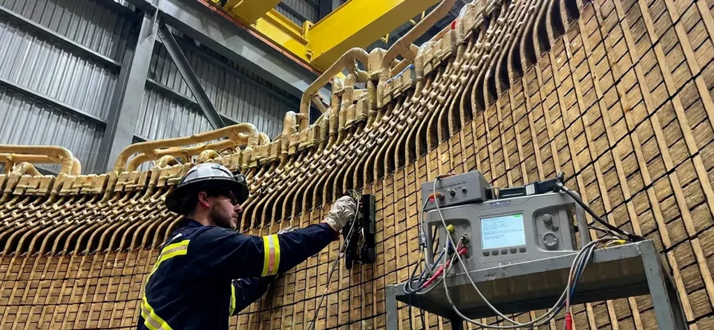
ELCID Test for Stator Cores: Electromagnetic Core Detection
Introduction
Large utility generators in coal, gas, nuclear, and hydro power plants depend on massive stator cores constructed from hundreds of thousands of thin, insulated silicon-steel laminations. These laminations form the magnetic circuit that is essential for efficient energy conversion. Over years of service, or because of manufacturing defects, handling damage, thermal cycling, vibration, or contamination, the thin inter-laminar insulation can degrade and allow electrical shorts between laminations. The resulting circulating eddy currents cause localized overheating (hot spots), core melting, winding insulation failure, and, in the worst cases, catastrophic generator outages that cost millions in lost revenue and repairs.
The ELCID test for stator cores (ELCID stands for Electromagnetic Core Imperfection Detector) is a modern, low-risk, offline diagnostic tool developed specifically to locate inter-laminar insulation defects in large generator and motor stator cores. It requires only a fraction of the power needed by traditional methods, and it has become the industry-preferred choice for factory acceptance, commissioning, routine maintenance, and post-repair verification.
Background
Stator core inter-laminar shorts have plagued large rotating machines since their inception. Two methods have dominated core testing: the traditional high-flux Ring/Loop test and, more recently, ELCID.
The Ring/Loop (Thermal Loop) Test and Its Drawbacks
For decades, the primary diagnostic method was the high-flux “Ring Flux” or “Loop” test, also called the thermal loop test. In this approach, the rotor is removed and a temporary high-voltage, high-current excitation winding is installed around the stator yoke. The winding energizes the core to near its rated operating flux density (approximately 94–100% of rated flux, or 1.5–1.8 tesla). This induces full service-level currents across any insulation faults and produces detectable hot spots, which are located using infrared thermography or thermocouples.
While effective at revealing surface-level overheating, the Ring/Loop test has significant drawbacks. It demands megawatt-class power supplies, heavy cables, skilled teams, strict safety protocols, and extensive setup, often three work shifts and 144–360 man-hours for a large turbo-generator. Critically, the high flux can exacerbate existing faults, cause additional core damage, or even initiate new shorts during the test itself. Deep-seated defects may also remain undetected if heat does not propagate to the surface.
How ELCID Changed Stator Core Testing
ELCID was pioneered in the 1980s by the UK’s Central Electricity Generating Board (CEGB) as a low-power, safer alternative. It operates at only 4% of rated flux (typically 0.01–0.02 T) and requires just 3 kVA for a 500 MW turbo-generator, or less than 5 kVA for large hydro units. As a result, ELCID eliminates heating risks entirely while offering superior sensitivity, even to deep faults within the core.
Modern portable digital systems, such as the Iris Power ELCID Evolution, complete testing in a single shift with one technician and 8–10 man-hours. This enables more frequent monitoring during shorter outages. ELCID is now routinely used worldwide alongside or in place of Ring/Loop testing because it is faster, cheaper, non-destructive, and compatible with robotic systems that allow testing with the rotor in place when air-gap space permits.
Need Maintenance Direction
and Support?
Place a Generex Technical Field Advisor on-site to oversee work, guide technicians, and protect your interests.
Theory of Operation
The ELCID test works by exciting the stator core with a very low magnetic flux and measuring the small fault currents that flow wherever the inter-laminar insulation has failed. The sections below explain how the low-flux excitation is applied, how a transformer analogy describes the fault currents, and how the PHASE and QUAD signals separate true, heat-generating faults from normal magnetizing current.
Low-Flux Excitation
The stator core relies on insulated laminations to minimize eddy-current losses. When the insulation fails, low-resistance paths form and allow fault currents that generate heat during normal operation. In the Ring/Loop test, full flux produces measurable thermal rises, but at high risk and high power cost.
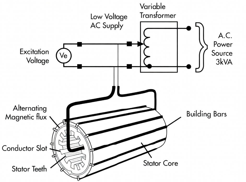
ELCID instead uses a temporary multi-turn excitation winding to create a low toroidal flux (4% of rated). This low flux induces tiny fault currents that cause negligible heating and are completely safe for the core, yet they still generate detectable electromagnetic signatures.
The Transformer Analogy
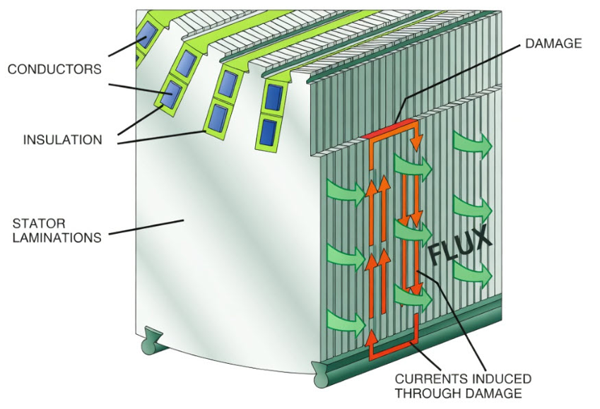
The operating principle becomes especially clear through a transformer analogy. The ELCID excitation winding wrapped around the stator yoke functions exactly as the primary winding of a transformer. The stator core itself is the transformer’s magnetic core, efficiently channeling the alternating flux. Any inter-laminar insulation defect creates a closed conductive loop of shorted laminations, which is precisely analogous to a shorted secondary winding in the transformer.
Just as in a real transformer, the changing magnetic flux produced by the primary induces a voltage in this fault loop. Because the fault loop is highly inductive (dominated by the magnetic circuit), the resulting fault current lags the primary flux (and the induced voltage) by exactly 90 degrees. This 90° phase-delayed current is the quadrature (out-of-phase) component that actually dissipates real power as heat in service. The quadrature current and the resulting secondary (fault) magnetic field follow the right-hand rule of magnetism.
PHASE and QUAD Signals
ELCID exploits this exact phase relationship with a specialized search coil (a Chattock potentiometer, or Maxwell’s worm) scanned axially along each pair of adjacent teeth. The coil measures the magnetic potential difference caused by axial fault currents on the core surface. The raw signal is fed into a phase-sensitive detector that electronically resolves it into two orthogonal components:
- PHASE (P): In phase with the excitation flux. It primarily reflects the normal magnetizing current required to establish flux in a healthy core.
- QUAD (Q): 90° out of phase (quadrature) with the flux. It is directly proportional to the resistive fault currents induced in any shorted “secondary” loops.
Only the QUAD signal is diagnostic of true, heat-generating faults. In a perfect core, the QUAD trace is a flat zero line, and any deviation indicates an imperfection. Because fault currents are in quadrature with the excitation, ELCID cleanly separates them from the much larger magnetizing current by differentiating the zero-crossing phase angle of each signal, which achieves high sensitivity.
Field comparisons confirm that ELCID detects deep-seated faults more reliably than the Ring/Loop test, which can miss them if heat does not reach the surface.
Test Procedure
ELCID testing is performed offline, typically with the rotor removed (although robotic variants allow rotor-in-place testing). The procedure is straightforward and low-risk:
- Preparation: Clean the stator bore thoroughly and visually inspect it for obvious damage. Install a lightweight temporary excitation winding around the yoke.
- Excitation: Energize the core to precisely 4% of rated flux using a standard mains supply. Verify the flux by calculation or by search-coil voltage.
- Scanning: Set the Chattock coil to span one tooth pair across a single slot. Scan axially from one end of the core to the other while recording the PHASE and QUAD signals versus position. Modern digital instruments automate logging and produce real-time traces. The ELCID Evolution™ made by Iris Power is the industry leader.
- Coverage: Test every slot pair on both ends of the core if accessible, and verify repeatability and symmetry. Test the step iron as well, using a specialized jig or cart.
- Demagnetization and Removal: Demagnetize the core by shutting off the excitation loop supply. Remove the excitation winding after testing.
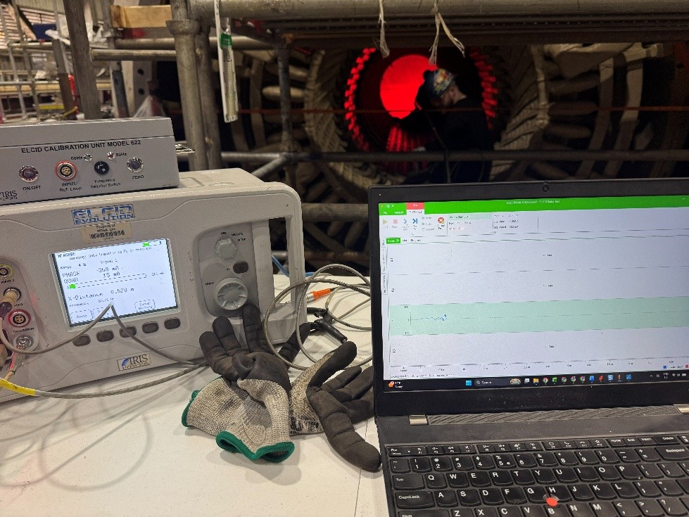
Compared with the Ring/Loop test’s multi-day, high-voltage setup and thermal imaging under full flux, ELCID is dramatically simpler and safer.
Interpreting ELCID Test Results
Results appear as PHASE and QUAD traces plotted against axial position for each slot. Interpretation follows established criteria.
Alert Threshold
At 4% flux, a QUAD signal exceeding ±100 mA is the industry-accepted alert level. This typically correlates to a 5–10°C temperature rise under full-flux operation, although the exact correlation depends on core geometry. Any QUAD signature over 50 mA calls for a detailed, up-close inspection of the indicated location, using the naked eye and a 10-power magnifying glass to look for signs of physical damage and localized overheating.
Polarity Check
True faults produce a QUAD signal of opposite polarity to the PHASE signal at the same location. Same-polarity deviations are usually benign, caused by construction variations or residual currents.
Fault Location and Severity
Correlate anomalies across adjacent slots. Characteristic peak and dip patterns pinpoint tooth-tip versus slot-bottom faults. Amplitudes greater than 180–200 mA indicate severe defects.
Trending
Compare results against baseline data from the factory or a prior outage. Increasing QUAD values signal progressive degradation.
Automated Analysis
Software generates color heat maps and flags suspect areas automatically. Because ELCID measures actual fault currents rather than secondary heat, it provides clearer, more repeatable results than infrared-based Ring/Loop testing.
Repair Scenarios
When ELCID identifies defects, repairs are planned according to severity and can be verified immediately.
Minor and Localized Faults
For faults below 150 mA over a small area, light surface grinding removes burrs, and the area is then finished with insulating varnish or epoxy. Re-test with ELCID after the repair.
Acid Etching for Minor to Moderate Faults
Minor to moderate faults can also be cleared with an acid-etching process. An AC or DC power supply energizes a wand with an absorbent pad wetted with an acid-water solution. The electro-etching removes the surface layer of metal in the damaged area until the fault clears.
Moderate Faults
Insert thin insulation sheets (mica paper, Nomex, or epoxy-glass) between laminations, or perform localized re-stacking. Confirm the repair with a repeat ELCID test and, optionally, a low-power thermal scan.
Severe and Widespread Faults
Faults above 200 mA over large areas require major core section replacement or full restacking. Because loss of core clamping pressure can lead to lamination fretting and inter-laminar shorts, pair these repairs with through-bolt and building-bolt checks.
Post-Repair Verification
Post-repair ELCID verification confirms that QUAD signals return below the threshold. Early intervention with ELCID prevents the need for costly full-core replacements and avoids the higher risks associated with attempting repairs after a damaging Ring/Loop test.
IEEE and ANSI Documentation
ELCID is formally recognized in IEEE Std 56-2016, IEEE Guide for Insulation Maintenance of Electric Machines. The guide describes the low-energy flux (ELCID) test method, setup parameters, interpretation criteria, and its role in stator-core evaluation. Supporting technical papers and best practices appear in IEEE conference publications and CIGRE references (for example, from 2004).
While ELCID is not covered by a standalone ANSI standard, IEEE documents are frequently dual-designated as ANSI/IEEE and serve as the global reference for utilities, OEMs, and service providers. Always consult the latest edition of IEEE 56 for current test parameters and safety guidance.
Summary and Conclusions
The ELCID test for stator cores represents a major advance over the traditional high-flux Ring/Loop test. By using only 4% flux and a few kVA of power instead of near-rated flux and megawatts, ELCID delivers a dramatically safer, faster, lower-cost, and more sensitive assessment of stator-core health without risking additional damage.
Its transformer-based understanding of fault currents (primary excitation, core flux path, and 90°-lagged secondary shorts), combined with phase-sensitive QUAD analysis, reliably detects even deep-seated inter-laminar shorts long before they cause operational hot spots. This enables proactive maintenance that extends generator life and prevents unplanned outages.
When combined with visual inspections, wedge-tightness testing, stator partial discharge testing, and trending, ELCID becomes a cornerstone of modern predictive maintenance programs for aging utility fleets. Utilities and service organizations should standardize on trained ELCID teams and digital equipment to maximize reliability and minimize downtime in an era of ever-increasing demand for uninterrupted power.

About the Author
Charles J. Wolfe is the Founder and Principal Engineer of Generex Consulting, with over 30 years of global experience in power generation. He is a recognized expert in generator and excitation systems, trusted by clients worldwide for solving complex engineering challenges.