AC Impedance Testing for Generator Rotors Explained
Introduction
The rotor (field) winding of a large utility generator is a critical component that must maintain electrical integrity under high centrifugal forces, thermal cycling, and vibration. Inter-turn shorts in the rotor winding can develop due to insulation abrasion, contamination, or manufacturing defects and may not be detectable by DC resistance or insulation-resistance (Megger) tests because the short may be intermittent or voltage-dependent.
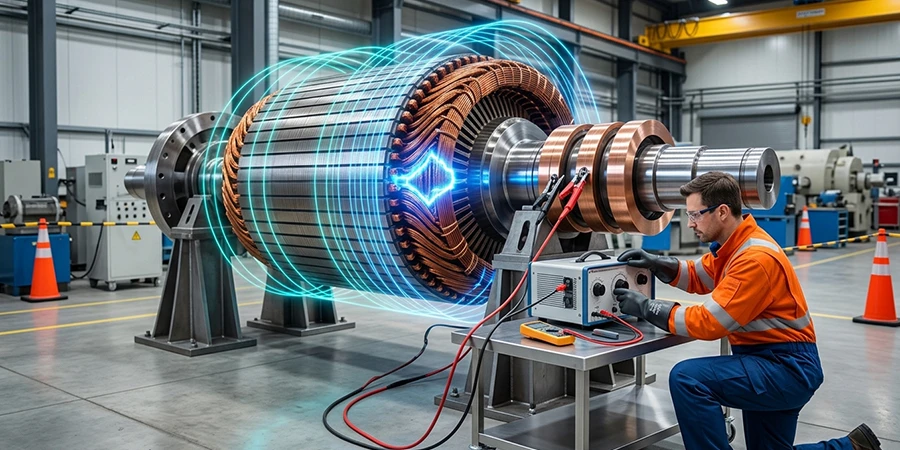
The AC Impedance Test (also called the Rotor AC Impedance Test or Impedance Drop Test) is a sensitive, offline diagnostic method that applies variable AC voltage to the rotor winding and measures impedance to detect these hidden turn-to-turn faults. By plotting impedance versus voltage, the test reveals sudden changes that indicate shorts, enabling early intervention before a ground fault or loss of excitation occurs.
Background
Rotor inter-turn shorts have been a known cause of generator outages since the early days of large synchronous machines. Traditional DC tests (resistance or hipot) often miss voltage-sensitive faults because low DC voltage does not overcome contact resistance at the short location. The AC Impedance Test emerged in the 1960s–1970s as a practical field method to expose these defects under AC conditions that more closely simulate operating stresses. It is now routinely performed during commissioning, major outages, post-repair verification, and root-cause failure investigations on turbo-generators and hydro-generators. The test is especially valuable for rotors with long operating histories or those showing vibration anomalies or abnormal field current.
Theory of Operation
The rotor winding can be modeled as a distributed inductance (L) in series with resistance (R). When an AC voltage (V) (typically 50/60 Hz) is applied, the measured impedance is:
Z = V/I = √(R² + (ωL)²)
where ω = 2πf is the angular frequency and I is the measured current.
In a healthy rotor, Z remains relatively stable or rises slightly with increasing voltage due to minor core saturation effects. If one or more turns are shorted, the effective number of turns decreases, reducing the inductance (L) and therefore lowering the overall impedance (Z). Power loss (measured as P = V × I × cos φ) also increases because circulating currents in the shorted turns produce additional I²R heating.
Why Impedance Jumps Suddenly When Voltage Is Raised
Many inter-turn shorts are voltage-dependent. At low test voltages, an oxide layer, carbon dust, or poor contact at the short location creates high resistance, so the fault remains effectively “open” and impedance appears normal. As voltage is increased to a critical threshold, the applied electric field overcomes the contact resistance, “closing” the short. This causes an abrupt reduction in effective L, producing a sudden drop (or “jump”) in measured impedance and a corresponding rise in current and power loss. The test therefore sweeps voltage in controlled steps (typically 5–10 V increments up to 120 V, depending on rotor size and supply power capabilities) to capture this characteristic knee in the impedance curve — something DC tests cannot reveal.
Test Procedure Overview
The test is performed offline with the rotor stationary (in place or removed). Key steps include:
- Preparation: Disconnect and isolate the rotor field leads. Ground the shaft and ensure the rotor is at ambient temperature. Verify slip rings and brush holders are clean if accessible.
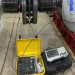
- Test Setup: Connect a variable AC voltage source (0–240 V, 50/60 Hz) across the rotor field terminals. Use precision instruments to measure voltage (V), current (I), power (P), and phase angle.
- Voltage Sweep: Gradually increase voltage in small steps (typically 5–10 V). At each step, stabilize and record current and voltage. Continue until the rated field voltage or a safe maximum is reached.
- Data Plotting: Plot impedance (Z) and power loss versus applied voltage. Compare with baseline (factory or previous outage) data.
- Safety: Limit test current to avoid overheating. Discharge windings after testing and follow lock-out/tag-out procedures. If the rotor is installed in the stator, ensure that nobody can access the high-voltage bushing/isophase connections, as AC voltage may be induced in the stator windings.
The complete test typically takes less than 1 hour from setup to tear-down.
Need Expert
Engineering Guidance?
Get independent technical advisory for your power generation project, from design review to project oversight.
Interpreting Results
Results are evaluated by comparing the impedance–voltage curve to OEM baselines and previous tests:
- Healthy Rotor: Impedance remains nearly constant or shows only a slight, smooth linear increase with voltage. Power loss rises gradually.
- Marginal: Small deviations or a slight downward trend in impedance at higher voltages.
- Faulty: Sudden, abrupt drop (“jump”) in impedance at a specific voltage threshold, accompanied by a sharp increase in current and power loss. The voltage at which the jump occurs indicates the severity or location of the short.
A significant deviation from baseline impedance or any visible knee in the curve is considered abnormal. Trending is essential — a progressive lowering of the impedance curve or an earlier onset of the jump indicates worsening inter-turn shorts.
Repair Scenarios
If results indicate faults:
- Minor Shorts (small impedance drop at high voltage, localized): Inspect accessible areas, clean contamination, or apply insulating varnish. Re-test after repair.
- Moderate Shorts (clear jump at mid-range voltage): Locate the fault using pole-drop or inter-pole voltage methods, then repair or replace the affected coils/turns.
- Severe/Widespread Shorts (large impedance drop at low voltage or multiple jumps): A full rotor rewind or pole-coil replacement is usually required.
Post-repair testing must include a repeat AC Impedance Test plus a 500 V Megger/P.I. test and, if appropriate, a reduced-voltage hipot test to confirm integrity before returning the rotor to service.
IEEE & ANSI Documentation
The AC Impedance Test for rotor inter-turn fault detection is described in IEEE Std 115-2019, IEEE Guide for Test Procedures for Synchronous Machines, which covers acceptance and performance testing of synchronous machines, including rotor impedance measurements. Supporting guidance appears in IEEE Std 56-2016, IEEE Guide for Insulation Maintenance of Electric Machines. While no standalone ANSI/IEEE standard is dedicated exclusively to the rotor AC impedance test, IEEE 115 is the primary reference and is frequently dual-designated as ANSI/IEEE. OEM technical information letters and EPRI reports also provide detailed procedures and acceptance criteria.
Summary & Conclusions
The AC Impedance Test is a powerful, voltage-sensitive diagnostic tool that detects inter-turn shorts in large utility generator rotors by revealing sudden impedance drops caused by voltage-dependent faults — something DC tests cannot identify. The electrical theory is straightforward: shorted turns reduce effective inductance, lowering measured impedance (Z = V/I), with the abrupt change occurring when applied voltage overcomes contact resistance at the fault site. When performed and interpreted according to IEEE Std 115, the test enables proactive repairs that prevent forced outages, loss of excitation, and costly rotor rewinds. As generator fleets age and face increasing cyclic operation, routine AC Impedance Testing has become an essential part of modern predictive maintenance programs, providing high diagnostic value at low cost and helping maintain the reliability of critical power assets.

About the Author
Charles J. Wolfe is the Founder and Principal Engineer of Generex Consulting, with over 30 years of global experience in power generation. He is a recognized expert in generator and excitation systems, trusted by clients worldwide for solving complex engineering challenges.