Automatic Voltage Regulator Inspection & Maintenance
Introduction
Inspection and maintenance of Automatic Voltage Regulators are vital elements of a comprehensive generator reliability program for large utility turbine-driven units. AVRs, whether analog, digital, or hybrid, are subject to thermal stress, electrical transients, vibration, and component aging. Routine inspection during outages, combined with functional testing and calibration, helps detect degradation before it affects generator performance or triggers protective trips.
Effective maintenance minimizes downtime, supports NERC reliability standards, and can defer costly full excitation system replacements. This article provides practical guidance on AVR inspection, testing, common failure modes, repair strategies, and documentation best practices tailored for utility-scale applications.
Background
Automatic Voltage Regulators (AVRs) are essential components of the excitation system in large utility turbine-driven synchronous generators. These regulators continuously monitor generator terminal voltage and adjust the DC field current supplied to the rotor winding to maintain stable output voltage under varying load conditions, grid disturbances, and operational transients.
In modern utility plants—whether fossil, combined-cycle, or nuclear—AVRs support critical functions such as reactive power control, voltage stability, and system reliability. Failure or degradation of an AVR can lead to voltage instability, loss of synchronism, reduced generator capability, or forced outages with significant economic impact. For consulting firms specializing in generator testing, inspection, and repair, expert AVR services provide high-value support by identifying issues early, optimizing performance, and extending the service life of aging excitation systems.
Theory of Operation
An AVR operates as a closed-loop feedback control system. It senses generator terminal voltage (typically via potential transformers), compares it to a reference setpoint, and generates a control signal that modulates the field excitation. In static excitation systems, the AVR controls thyristor or IGBT-based converters; in brushless systems, it regulates the exciter field.
Key control elements include proportional-integral-derivative (PID) algorithms, voltage droop compensation for parallel operation, and limiters for overexcitation (OEL), underexcitation (UEL), and volts-per-hertz (V/Hz) protection to prevent overheating or core saturation. Modern digital AVRs incorporate advanced features such as power system stabilizers (PSS) for damping oscillations and adaptive tuning for improved dynamic response. The regulator must respond rapidly—often within milliseconds—to maintain voltage within ±0.5% of nominal while handling disturbances like load rejection or grid faults. Proper tuning ensures stability margins and compliance with grid codes.
Maintenance Procedures
AVR maintenance follows a structured approach during planned outages or when performance anomalies are observed.
- Safety and Preparation — Lockout/tagout the excitation system, verify zero energy, and isolate the AVR from the main field circuit. Review OEM manuals and previous outage reports.
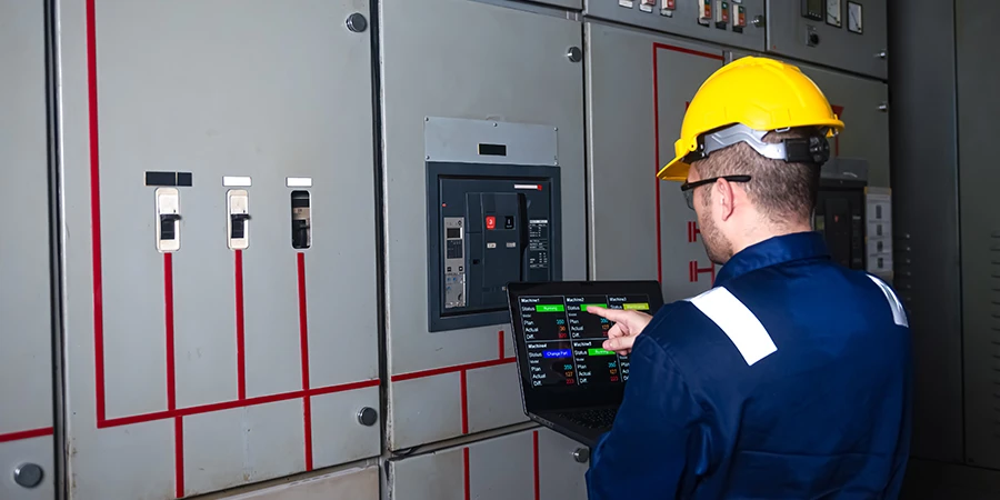
- Visual and Physical Inspection — Examine the AVR enclosure, printed circuit boards, wiring, connectors, cooling fans, and power supplies for signs of overheating, corrosion, dust accumulation, loose connections, or burnt components. Check for proper grounding and shielding.
- Functional Testing — Perform offline tests including voltage sensing accuracy, reference setpoint adjustment, response to step changes, limiter operation (OEL, UEL, V/Hz), and protective functions. Use manufacturer-recommended test sets or simulation tools for digital AVRs.
- Calibration and Tuning — Verify and adjust gain settings, time constants, and droop characteristics. For digital systems, download configuration files and compare against baseline data.
- Cleaning and Component Replacement — Clean dust and debris; replace aging electrolytic capacitors, fans, or power supplies as preventive measures.
- Online Monitoring Review — Analyze trend data from historian systems for voltage stability, field current behavior, and alarm history.
Procedures are recommended every 2–4 years or after major disturbances. Digital AVRs often allow partial online diagnostics, reducing outage scope.
Excitation System Issues?
Test, inspect, and troubleshoot static and brushless excitation systems to keep your unit running reliably.
Common Issues and Remedies
Understanding common issues helps identify potential faults early and supports reliable generator voltage regulation and stable operation.
Common Issues
Common AVR problems in large utility generators include voltage instability, failure to build up voltage, over/under-excitation, and complete loss of regulation. Voltage fluctuations or hunting often stem from improper tuning, worn sensing transformers, or feedback loop instability. Overheating results from poor ventilation, high ambient temperatures, or overloaded power supplies. Component failures—particularly electrolytic capacitors, thyristors, or IGBT modules—are accelerated by thermal cycling and electrical surges. Contamination from dust, moisture, or oil ingress causes tracking or short circuits. Aging analog systems may suffer from drift in potentiometers or op-amps.
Remedies
- Tightening connections and replacing degraded wiring or fuses.
- Cleaning and resealing enclosures to prevent ingress.
- Replacing failing capacitors or power modules with OEM or upgraded equivalents.
- Retuning PID parameters or updating firmware in digital systems for better stability.
- Installing surge protection or improving cooling if recurrent overheating occurs.
Early detection through routine inspection prevents escalation to generator trips or reduced reactive capability.
Repair Scenarios
Repair scope depends on inspection and test findings.
Minor Repairs
Minor repairs cover loose connections, minor contamination, or a single-component failure such as a capacitor or fan replacement, typically completed on-site during a short outage of one to three days.
Moderate Repairs
Moderate repairs address degraded boards, drifted calibration, or partial power supply failure, and involve module replacement, full recalibration, and functional verification over three to seven days.
Major Repairs
Major repairs are required for widespread board damage, obsolete analog system failure, or repeated limiter malfunctions, and typically involve complete AVR replacement or an upgrade to a modern digital system with PSS and enhanced diagnostics, including commissioning, over one to three weeks.
Upgrades to digital AVRs often improve performance, add monitoring capabilities, and extend system life. All repairs must include post-work testing under simulated or actual load conditions and verification of protective limiters. Compatibility with the existing exciter and generator rotor characteristics is critical.
IEEE & ANSI Documentation
Industry standards guide AVR inspection, testing, and maintenance. IEEE Std 421.1 provides definitions for excitation systems, while IEEE Std 421.2 offers guidance on identification, testing, and evaluation of dynamic performance of excitation control systems. IEEE Std 421.5 recommends models for excitation systems used in power system stability studies, aiding in tuning and verification. IEEE C50.13 (Standard for Cylindrical-Rotor Synchronous Generators) and IEEE Std 115 (Test Procedures for Synchronous Machines) address overall generator testing that includes excitation system performance.
ANSI/IEEE C37.102 (Guide for AC Generator Protection) discusses protection coordination involving AVR limiters. Thorough documentation—recording test results, settings, as-found/as-left conditions, photographs, and trend data—ensures compliance with NERC requirements, supports root-cause analysis, and maintains an auditable maintenance history. Digital AVR configuration files should be backed up and version-controlled.
Summary & Conclusions
Automatic Voltage Regulators play a central role in maintaining voltage stability, reactive power support, and reliable operation of large utility turbine-driven generators. Systematic inspection and maintenance—encompassing visual checks, functional testing, calibration, and timely component replacement—enable early detection of issues such as component degradation, tuning drift, or contamination before they cause voltage instability or outages.
Adherence to IEEE Std 421 series guidelines and related ANSI standards, combined with meticulous documentation, ensures regulatory compliance and optimal performance. For utilities managing aging excitation systems amid increasing cyclic operation and grid demands, proactive AVR programs delivered by specialized consultants deliver substantial returns through improved reliability, reduced forced outages, and extended equipment life. Implementing the procedures outlined here strengthens overall generator availability and supports long-term asset management objectives.

About the Author
Charles J. Wolfe is the Founder and Principal Engineer of Generex Consulting, with over 30 years of global experience in power generation. He is a recognized expert in generator and excitation systems, trusted by clients worldwide for solving complex engineering challenges.