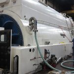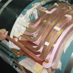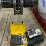
DC Leakage & DC Hipot Tests for Generators Explained
Introduction
Here’s a clear, layman’s explanation of the DC Leakage Test and DC Hipot (High Potential) Test on large utility generators, using the same garden hose analogy as the Megger + P.I. explanation. All relevant IEEE and ANSI standards that govern these tests have been incorporated.
The Garden Hose Analogy — Taking It Further
Remember the basic Megger test: you turn on the faucet (apply voltage) to the capped garden hose and watch the water flow. At first, water rushes in rapidly to fill and stretch the hose walls (charging current). Once pressure equalizes, any continued flow is leakage through imperfections in the hose wall.
- The DC Leakage Test is like carefully watching and measuring that steady leakage flow after the hose has fully pressurized — but you do it at gradually higher pressures in controlled steps.
- The DC Hipot Test is like cranking the faucet pressure much higher (well above normal operating pressure), holding it there, and seeing if the hose holds without bursting or spraying massive leaks. It’s a proof test — a strict go/no-go check to confirm the insulation can safely withstand voltage stresses.
Terminology Clarification
“Hipot” terminology can be confusing. The “hipot” device used to perform the DC Leakage test and the “Hipot” test is often referred to as “the Hipot set.” The main test is the DC Leakage test, and the “Hipot test” is actually just the final voltage step on a DC Leakage test. Both tests use direct current (DC) at much higher voltages than a standard Megger.
When someone says they want to “hipot” the generator, the most important thing to establish is what the maximum voltage of the DC Leakage test series will be. This stopping point is the hipot step.
What Is the DC Leakage Test?
This is a more detailed diagnostic extension of the insulation resistance test. You apply high DC voltage in controlled steps (or a slow ramp) and measure the steady leakage current once everything has stabilized. It reveals exactly how much current is sneaking through cracks, moisture, dirt, voids, or aging material in the insulation after the initial charging currents have died away.
What Is the DC Hipot Test?
“Hipot” stands for high potential (high voltage). This is the actual withstand or proof test:
- Voltage is raised (often in steps) to a final high target level.
- It is held for a required time (usually 1 minute at the maximum voltage).
- The winding either passes (no breakdown, flashover, or excessive leakage) or fails (sudden arc, flash, or trip on high current).
Why These Tests Matter
After the hose is fully pressurized, any extra flow equals leakage through weak spots. Raising pressure in steps lets you see whether small leaks stay small or suddenly worsen. Cranking the pressure way up (hipot) proves the hose can handle surges and long-term stress without rupturing.
How the Tests Are Performed in Practice
These tests are performed only during planned outages with the generator shut down, locked out, and safely isolated. A satisfactory Megger + P.I. test (typically P.I. ≥ 2.0 per IEEE 43) is usually completed first as a prerequisite.
The Stepped Voltage Procedure
The stepped voltage procedure is the most common and safest method:
- Technicians select an N value — simply the number of equal voltage steps (commonly 5 to 10 steps for large utility generators).
- Example: If the final test voltage is 50 kV and N = 5, each step increases by 10 kV.
- This N value directly creates the time table for the hold — a schedule that dictates exactly how long to hold at each voltage step (typically 30–60 seconds or 1 minute per step) plus a final 1-minute hold at full voltage.
Why Wait Between Voltage Steps?
Immediately after increasing to the next voltage, there is still a temporary surge of charging current and polarization (absorption) current while the insulation “stretches” to the new electric field. Waiting allows these transient currents to decay, so the measured current reflects true, steady leakage current only.
This mirrors waiting for the garden hose to stop expanding after raising the faucet supply pressure, before timing how much water is actually leaking out.
Why we use the factor of 1.7 for converting AC to DC test voltages based on IEEE and ANSI guidance will be discussed in detail later in this article.
Choosing a Test Voltage
Factory acceptance tests for new machines are typically specified in AC rms voltage (e.g., 2E + 1,000 V AC, where E = rated line-to-line kV). AC voltage alternates positive and negative, so its peak stress on the insulation is about 1.414 times (√2) the rms value.
To create an equivalent DC test that applies roughly the same (or slightly more conservative) constant peak stress, standards apply a multiplier of approximately 1.7:
DC test voltage ≈ 1.7 × (2E + 1,000) V (or a reduced percentage of that value for routine maintenance testing on in-service machines).
The 1.7 factor provides a small safety margin because DC applies constant unidirectional stress without the reversing polarity of AC.
For household power, we say the power is at 120 volts. But that’s not entirely true — this is the root-mean-square (RMS) voltage. The RMS voltage is a sort of average voltage throughout one cycle, calculated as the peak voltage divided by the square root of 2, which is 1.41. This means that the peak voltage in the wall circuit is actually 120 × 1.41 = 169 volts. The insulation must be able to withstand the full 169 volts!
Similarly, a 13,800-volt winding actually experiences a peak voltage of 13,800 × 1.41 = 19,500 volts, and the test voltages at DC conditions must replicate (and exceed) this voltage in order to qualify the winding for reliable operation.
Older machines or risk-averse customers may elect a lower test voltage, but remember: taking less risk today during the test only puts off more risk to tomorrow. Taking more risk today gives you more certainty into the future.
The whole idea of doing the hipot test during outage conditions is to identify and correct any weaknesses during controlled conditions, where any fault currents would be in the milliamp range. Oftentimes, faults during full-load operation can do catastrophic damage requiring much more extensive repairs, up to and including rewind and even stator core restacking.
Test Procedure Overview
1. Connect the DC test set (positive lead to the winding, return to the generator frame/ground).
2. Raise voltage in N equal steps according to the time table.
3. At each step, wait the required hold time and record leakage current.
4. At the final voltage, hold for 1 full minute while monitoring.
5. Reduce voltage slowly and fully discharge the windings (they can hold a dangerous charge).
Reading the Results
DC Leakage Test Results
- Good: Leakage current rises slowly and stays roughly linear (or very flat) with increasing voltage.
- Bad: Sudden sharp jumps, a “knee” in the curve, or current that keeps climbing rapidly — this indicates hidden damage such as contamination, voids, or tracking paths.
DC Hipot Test Results
- Pass: Holds the full test voltage for the required time with no breakdown and acceptable leakage current.
- Fail: Arcing, flashover, or protective trip on high current — the insulation has a critical weakness.
Trending leakage current values from previous tests is very valuable for early warning.
What to Do About the Results
Good/Passing Results
The insulation has adequate dielectric strength. The generator can be returned to service. Maintain good records and continue trending.
Bad/Failing or Marginal Results
- Do not return the machine to service without further action.
- Most issues are fixable: thorough cleaning and drying of the windings, followed by retesting.
- If problems persist, perform advanced diagnostics (e.g., partial discharge or tan-delta testing) or plan for localized repair or rewind.
Need Expert
Engineering Guidance?
Get independent technical advisory for your power generation project, from design review to project oversight.
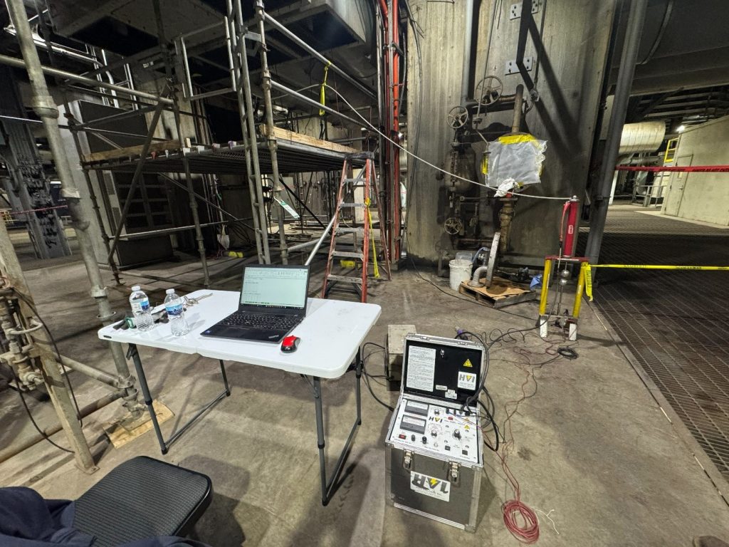
Why We Use a Sphere Gap Set
We use a sphere gap set for two main practical reasons during generator insulation testing:
1. Accurate Verification/Calibration of the Applied Voltage (Primary Reason) — Modern DC hipot test sets have built-in digital voltmeters, but at very high voltages (tens to hundreds of kV), these meters can have some error or drift. The sphere gap provides an independent, physics-based check of the actual peak voltage being applied to the generator winding.
2. Overvoltage Protection — The sphere gaps will flash over if the test set is pushed beyond the flashover voltage of the sphere gap set, preventing accidental operator error that could otherwise cause the unit to fail.
A sphere gap set also makes a nice-looking trophy for the generator specialist to proudly display wherever they go — and customers and industrial tourists passing by think they look really cool.
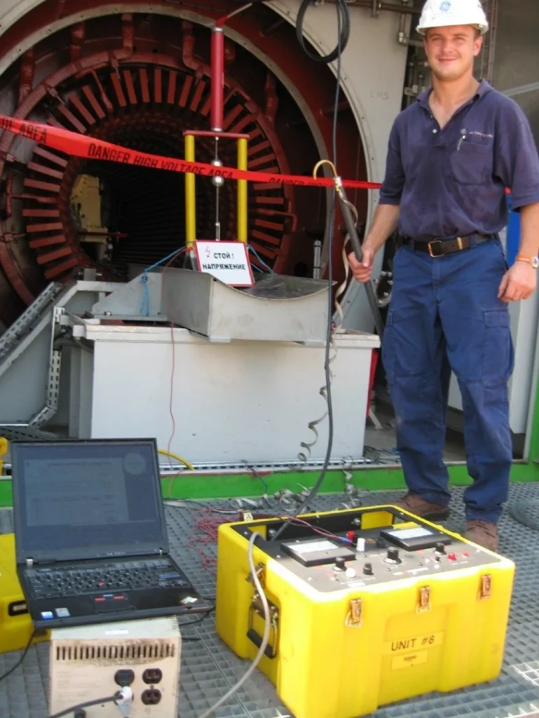
Setting the Sphere Gaps
- You set the spheres to a specific gap distance that corresponds to the target test voltage (from standard tables in IEEE Std 4 or IEC 60052).
- Slowly raise the voltage from the test set until the sphere gap just sparks over.
- If the test set’s voltmeter reads very close to the expected value when the gap sparks, you know your voltage reading is accurate.
- This is especially important for the final hold voltage in a hipot test or at each step in a leakage test.
Why Spheres, Specifically?
- The electric field between two spheres is very uniform (smooth and predictable) when the gap is not too large.
- Spark-over voltage is almost independent of humidity, waveform shape, or minor surface contamination (unlike needle gaps, which are erratic).
- It gives consistent results within about ±3% accuracy when used correctly.
- It works equally well for DC, AC, or impulse voltages.
Controlling Standards and Documentation
The following IEEE and ANSI standards govern procedures, voltage levels, interpretation, and safety for DC leakage and DC hipot testing on large utility generators:
- IEEE Std 95 (latest widely referenced: IEEE 95-2002, reaffirmed 2007/2008) — This is the primary standard for DC high-voltage testing. It provides uniform methods for proof tests and diagnostic tests on stator windings of AC electric machines rated 2,300 V and above. It details the stepped/ramp procedures, the use of N steps, hold times, leakage current analysis, the 1.7 AC-to-DC conversion factor, and guidance on interpreting current-vs.-voltage curves.
- IEEE Std 43 (latest: IEEE 43-2013) — Covers the prerequisite insulation resistance (Megger) and Polarization Index (P.I.) tests. It is routinely referenced as a required first step before proceeding to DC hipot and provides minimum acceptable values and temperature correction guidance.
- ANSI/NETA ATS (Acceptance Testing Specifications, latest: 2025) and ANSI/NETA MTS (Maintenance Testing Specifications, latest: 2023) — These are the practical field standards used by testing companies and utilities. They specify when and how to perform DC hipot and leakage tests on rotating machinery, reference IEEE 43 and IEEE 95 directly, and provide tables for minimum insulation resistance values and test voltages.
Other related standards sometimes referenced include:
- IEEE Std 56 — Guide for insulation maintenance of large AC rotating machinery.
- IEEE Std 115 — Test procedures for synchronous machines (overall generator testing context).
- IEEE Std 433 — For very low frequency (VLF) testing as an alternative to power-frequency or DC hipot in some cases.
Always use the latest approved versions at your plant, and follow any additional requirements from the generator OEM (e.g., GE, Siemens) or your utility’s internal procedures.
Conclusions and Summary
- The DC Leakage Test (stepped or ramped) gives you a precise diagnostic picture of how much “water” is leaking at increasing pressures.
- The DC Hipot Test is the final tough pressure-proof: does the hose hold when you really crank it up?
- The N value determines the number of steps and creates the safe hold time table.
- Waiting after each step ensures you measure real leakage (not transients).
- The 1.7 factor fairly converts familiar AC test levels into equivalent DC stress with a safety margin.
- These tests are more aggressive than the 5 kV Megger + P.I., so they are performed by qualified technicians following strict safety protocols (PPE, barriers, proper discharging).

About the Author
Charles J. Wolfe is the Founder and Principal Engineer of Generex Consulting, with over 30 years of global experience in power generation. He is a recognized expert in generator and excitation systems, trusted by clients worldwide for solving complex engineering challenges.