Rotor Radial Stud Seal Testing: Procedure, Standards & Repairs
Introduction
In hydrogen-cooled large utility generators, the rotor field winding is supplied with excitation current through radial studs (or collector studs) that penetrate the rotor shaft. These studs must be sealed to prevent hydrogen leakage from the pressurized rotor interior into the atmosphere or oil system.
The rotor radial stud seal test is a specialized leak-detection procedure that verifies the integrity of the O-ring, gasket, or packing seals around these radial studs. It ensures the rotor remains gastight — maintaining hydrogen purity, preventing explosive mixtures, and avoiding oil contamination or pressure loss that could lead to reduced cooling efficiency, winding overheating, or safety hazards.
Background
Hydrogen-cooled generators operate with internal hydrogen pressures of 30–60 psig to reduce windage losses and improve cooling. Radial studs provide the electrical path from the slip rings (or exciter) to the field winding and often carry cooling gas passages.
Over time, thermal cycling, vibration, and seal aging can cause O-ring extrusion, hardening, or cracking — leading to leaks. Early rotor designs relied on visual inspection or operational hydrogen consumption monitoring, but dedicated seal testing became standard in the 1980s and 1990s as machines grew larger and reliability demands increased.
The test is routinely performed during major outages, post-rewind verification, or when hydrogen purity or consumption rates indicate possible leakage. For related diagnostic work, see our guide on generator cooling issues and fixes.
Theory of Operation
The radial stud seals form a pressure boundary between the hydrogen-filled rotor cavity and the external environment. The test treats the stud and seal assembly as a sealed pressure vessel — any leakage path allows gas to escape, causing measurable pressure decay or detectable tracer gas escape.
The underlying fluid-dynamic theory relies on the ideal gas law and leak-rate equations. For a pressure decay test:
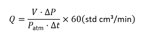
Where V is the internal volume of the test cavity (stud cavity), ΔP is the pressure drop, P is atmospheric pressure, and t is test duration.
Vacuum decay or helium tracer gas methods increase sensitivity by using larger pressure differentials or mass-spectrometer detection of helium molecules (atomic mass 4) at leak rates as low as 10⁻⁹ atm·cc/s.
Test Procedure
The test is performed offline with the rotor stationary — either in place or removed. Key steps include:
Preparation
Isolate the rotor field leads and any cooling gas passages. Remove or cap external connections to the radial studs. Clean accessible stud heads and seal areas.
Test Setup
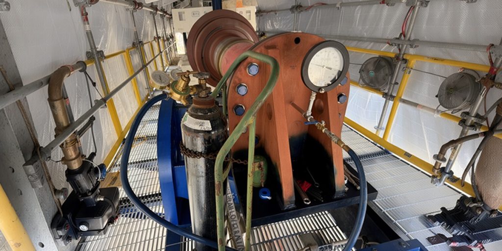
Install temporary test caps, adapters, or plugs on the exposed ends of the radial studs to create a sealed test volume. Connect the test rig — pressure/vacuum pump, gauges, and helium source if required.
Pressure and Vacuum Decay Test
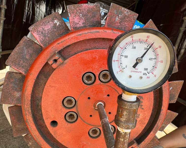
Pressurize the stud cavity with dry air or nitrogen at an OEM-approved pressure. Isolate the volume and monitor pressure change over one hour.
Helium Tracer Gas Test
If decay tests indicate leakage, pressurize with a helium–air mixture and scan the external seal area with a mass-spectrometer sniffer probe, or place the assembly in vacuum-chamber mode.
Safety
Purge with nitrogen before testing and follow full lock-out/tag-out procedures.
For complementary rotor diagnostics, review our procedures on the AC impedance test for generator rotors and the 500-volt megger polarization index test for generator rotors.
Interpreting Results
- Acceptable: Leak rate below OEM limits — typically no detectable leakage within one hour.
- Marginal: Leak rate near the upper limit, or slow decay that may worsen under operating pressure and temperature.
- Unacceptable: Rapid pressure drop (greater than 1 PSI/hour), visible bubbles, audible leaks, or oil residue around studs — all usually indicate failure.
Trending against previous outages is critical — increasing leak rates indicate progressive seal degradation. Pairing seal-test trending with vibration monitoring and turbine-generator troubleshooting provides a fuller picture of rotor health.
CTA PLACEMENt
Need Maintenance Direction
and Support?
Place a Generex Technical Field Advisor on-site to oversee work, guide technicians, and protect your interests.
Repair Scenarios
If test results are unacceptable, the repair scope depends on the severity of leakage:
Minor Leaks
Localized, low-rate leaks call for replacing individual O-rings, gaskets, or packing material on the affected stud. Re-test the repaired stud before proceeding.
Moderate Leaks
Multiple studs or a moderate leak rate require overhauling seal assemblies, replacing worn studs or hardware, and performing full rotor cleaning and purging.
Severe Leaks
Widespread or high-rate leaks may require major rotor disassembly, including stud replacement, seal groove rework, or a complete rotor rewind if associated winding damage is found.
All repairs must be followed by a complete repeat radial stud seal test — plus complementary rotor tests such as RSO, pole drop, and Megger polarization index testing — before returning the unit to service. In many cases, a DC leakage and DC hipot test is also warranted to confirm winding condition.
IEEE and ANSI Documentation
Rotor seal integrity testing, including radial stud seals, is addressed in:
- IEEE Std 115-2019 — IEEE Guide for Test Procedures for Synchronous Machines
- IEEE Std 56-2016 — IEEE Guide for Insulation Maintenance of Electric Machines (rotor maintenance and hydrogen system integrity checks)
Supporting practices appear in EPRI reports on generator rotor maintenance and in OEM technical information letters. While no standalone ANSI or IEEE standard is dedicated exclusively to radial stud seal testing, IEEE 115 and IEEE 56 are the primary consensus references and are frequently dual-designated as ANSI/IEEE.
Summary and Conclusions
Rotor radial stud seal testing is a critical leak-detection procedure that ensures the gastight integrity of the seals around radial studs in hydrogen-cooled generator rotors. By using pressure decay, vacuum decay, or helium tracer gas methods, the test quantifies leakage and prevents hydrogen loss, purity degradation, and safety risks.
When performed and interpreted according to IEEE 115 and IEEE 56, it enables proactive seal replacement or repair that maintains rotor reliability and avoids costly forced outages. As generator fleets age and hydrogen-cooled designs remain prevalent in high-output machines, routine radial stud seal testing has become an indispensable part of modern predictive maintenance programs — delivering high value through simple, repeatable procedures that protect both equipment and personnel.
OEM procedures such as OMM-124 provide more detailed guidance on how to proceed.

About the Author
Charles J. Wolfe is the Founder and Principal Engineer of Generex Consulting, with over 30 years of global experience in power generation. He is a recognized expert in generator and excitation systems, trusted by clients worldwide for solving complex engineering challenges.