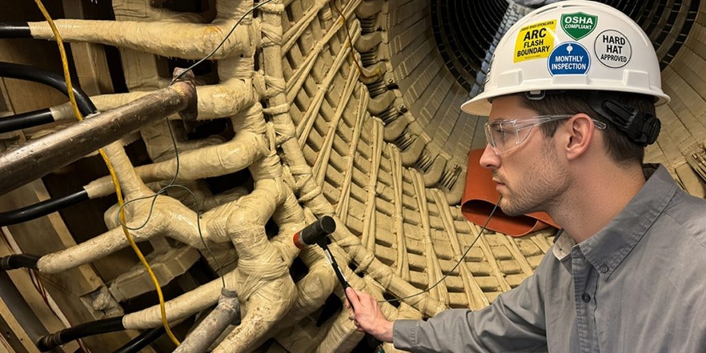
End Winding Bump Test and Modal Analysis
Introduction
Large utility generators operate under powerful electromagnetic forces that act on the stator end windings at line frequency (50/60 Hz) and twice line frequency (100/120 Hz). These forces can excite mechanical resonances in the cantilevered end-winding structure, leading to high-cycle fatigue, insulation cracking, loose ties and blocks, phase-connection failures, and, eventually, catastrophic winding failure.
The end winding bump test (also called the impact test), combined with modal analysis, is a non-destructive, offline vibration diagnostic method. It identifies the natural frequencies, damping ratios, and mode shapes of the stator end windings and phase connections.
Terminology clarification: The “bump test” refers specifically to the impulse excitation technique, in which a calibrated modal hammer strikes the end windings while accelerometers measure the response. Modal analysis (or experimental modal analysis, EMA) is the broader engineering process that uses the bump-test data to extract modal parameters: natural frequencies, damping ratios, and mode shapes.
When applied to stator end windings and phase connections, the two are usually performed together. Industry literature often refers to them interchangeably as “end-winding bump testing” or “stator end-winding modal analysis.”
Background
End-winding vibration problems have been documented since the early days of large turbo-generators and hydro-generators. Early diagnostics relied on visual inspection and simple “tap tests,” but these were subjective and could not quantify resonances. The modern bump test and modal analysis emerged in the 1980s–1990s, as digital signal processing and multi-channel analyzers became available.
Today, the test is routinely performed during factory acceptance, commissioning, major outages, post-rewind verification, and root-cause failure investigations. It is especially critical for aging fleets and high-speed two-pole machines, where electromagnetic forcing at twice line frequency is strong.
The consequences of an unnoticed resonance are well documented. In a 300 MW GE stator failure investigated by Generex, loosened and unsupported spans in the collector-end connection rings drifted into resonance at twice line frequency, causing strand breakage and ultimately a full stator rewind.
The goal of the test is to ensure that no dangerous natural frequencies lie near operating harmonics, preventing resonance-induced fatigue that can destroy windings within months or years.
Theory of Operation
The stator end windings behave mechanically as a complex, lightly damped structure supported by the core and bracing system. Electromagnetic forces at line frequency and twice line frequency act as periodic excitation. If a natural frequency of the end-winding basket or phase connections coincides with these forces, resonance occurs and vibration amplitudes are amplified dramatically.
The bump test excites the structure with a short-duration impulse from an instrumented modal hammer (the force input). Accelerometers mounted at multiple locations capture the acceleration response. The key measurement is the frequency response function (FRF):
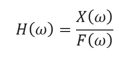
where:
- X(w) is the Fourier transform of the response acceleration (winding vibration).
- F(w) is the Fourier transform of the force input (hammer blow).
- H(w) is the frequency response function (transfer function) of the test specimen, in this case the winding.
To obtain frequency-domain data from time-domain signals, the Fast Fourier Transform (FFT) is used. The FFT is an efficient algorithm (Cooley–Tukey) for computing the Discrete Fourier Transform (DFT) of a sampled signal:

where x(n) is the discrete time-domain signal, N is the number of samples, and
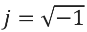
is the imaginary unit (written as i in mathematics).
The FFT reduces computational complexity from O(N2) to O(NlogN), enabling real-time spectral analysis on portable instruments.
Peaks in the FRF magnitude indicate natural frequencies. A phase shift through 90° at the peak, together with coherence close to 1, confirms a true mode. Damping is extracted using the half-power bandwidth or circle-fit methods, and mode shapes are constructed by repeating the test at many points (the roving-hammer or roving-response technique).
Need Expert
Engineering Guidance?
Get independent technical advisory for your power generation project, from design review to project oversight.
End Winding Bump Test Procedure
The test is performed offline with the rotor removed (or with the rotor in place for some robotic systems). The typical steps are:
- Preparation: Clean the accessible end-winding surfaces. Install triaxial accelerometers at representative locations (nose, knuckles, phase connections, and circuit rings). Use beeswax, sticky clay, or electrical duct seal for temporary attachment.
- Excitation: Use a calibrated modal hammer with a soft or medium tip to deliver repeatable impulses in the radial, tangential, and axial directions. Strike a grid of points (often 20–50 locations per end) covering the entire basket.
- Data acquisition: Record simultaneous force and acceleration time histories with a multi-channel FFT analyzer (typically 4–16 channels, with a sampling rate of at least 2 kHz). Average 3–5 impacts per point to improve the signal-to-noise ratio.
- Modal analysis: Process the data to generate FRFs, identify natural frequencies and damping ratios, and construct animated mode shapes using specialized software.
- Safety and cleanup: Demagnetize if necessary, and remove the sensors.
A full test on a large generator can be completed in one shift by a two-person team.
Interpreting End Winding Bump Test Results
Results are presented as FRF plots, coherence functions, and animated mode-shape videos. The key interpretation criteria (per IEEE 1665 and industry practice) are:
- Natural frequencies: Avoid resonances in the “exclusion band” around twice line frequency (for example, 115–135 Hz for 60 Hz machines and 95–115 Hz for 50 Hz machines). Some utilities also watch 1× running speed.
- Damping: Low damping (below 2–3%) at critical frequencies indicates a high amplification risk.
- Mode shapes: Global basket modes (e.g., 2-node ovaling) or local bar and phase-lead modes that produce relative motion between bars are unacceptable.
- Driving-point vs. transfer FRFs: High mobility (large response per unit force) at any point signals looseness or poor support.
- Trending: Compare the results with baseline data (factory or prior outage). Frequencies shifting downward, or amplitudes increasing, indicate progressive loosening.
Software automatically flags modes within exclusion zones and generates color-coded risk maps.
Repair Scenarios
If the results indicate unacceptable resonances or looseness, the corrective action depends on severity:
- Minor issues (local high mobility or a slight frequency shift): Retighten the blocking, add or replace ties and bracing, apply additional resin, or install additional support rings. Re-test immediately.
- Moderate issues (a global mode near twice line frequency): Install tuned mass dampers, stiffen the end-winding basket with additional braces, or perform localized re-blocking.
- Severe issues (multiple resonances in the exclusion band or very low damping): Redesign the full end-winding support system, re-tape, or perform a complete stator rewind with improved bracing geometry.
Post-repair bump testing is mandatory to verify that natural frequencies have shifted out of the exclusion band and that damping has improved.
IEEE and ANSI Documentation
The primary reference is IEEE Std 1665-2024 (and the 2009 edition), IEEE Guide for the Rewind of Synchronous Generators, 50 Hz and 60 Hz, Rated 1 MVA and Above, which explicitly discusses frequency-response (bump) testing of stator end windings and provides acceptance guidance.
Additional best-practice information appears in EPRI Report 3002016240, Generator Stator Endwinding Bump Test Guide, and in numerous IEEE conference papers on experimental modal analysis. While no standalone ANSI/IEEE standard is dedicated solely to the bump test, IEEE 1665 is the recognized consensus document. CIGRE and IEC working groups (e.g., IEC TC2 WG32) also reference these methods.
Summary and Conclusions
The end winding bump test and modal analysis provide a safe, repeatable, and highly informative assessment of the mechanical integrity of stator end windings and phase connections in large utility generators. By using calibrated impulse excitation and FFT-based frequency-response analysis, the test identifies dangerous resonances before they cause fatigue failures under electromagnetic forcing at line and twice-line frequencies.
When performed and interpreted according to IEEE 1665, the method enables utilities to schedule targeted repairs, avoid unplanned outages, and extend generator life. As fleets age and operating demands increase, routine bump testing combined with online vibration monitoring has become an essential element of modern predictive maintenance programs, ensuring reliable and safe operation of critical power assets.

About the Author
Charles J. Wolfe is the Founder and Principal Engineer of Generex Consulting, with over 30 years of global experience in power generation. He is a recognized expert in generator and excitation systems, trusted by clients worldwide for solving complex engineering challenges.