Capacitance Mapping Test on Liquid-Cooled Stator Windings
Introduction
In water-cooled (liquid-cooled) stator windings, cooling water flows through hollow copper strands inside each stator bar. The ground-wall insulation between the copper conductor and the stator core is designed to remain completely dry. If water leaks into the insulation — because of strand cracks, degraded brazes, or aging coatings — it causes a serious problem. Water has a very high dielectric constant compared with dry insulation, so it directly increases the capacitance of the bar-to-ground insulation system.
The capacitance of a parallel-plate capacitor, a good model for a stator bar to core, is given by:
C = ε (A / d) = εᵣ ε₀ (A / d)
Where:
- C = capacitance (farads)
- εᵣ = relative permittivity (dielectric constant) of the material between the plates
- ε₀ = permittivity of free space (8.85 × 10⁻¹² F/m)
- A = effective area of the conductor facing the core (the cap-map wand foil area)
- d = thickness of the insulation
Key values:
- Dry insulation (mica-epoxy or similar): εᵣ ≈ 3 – 5
- Water-contaminated insulation: εᵣ ≈ 80
This means that even a small amount of water can increase the capacitance to roughly 16 – 26 times that of dry insulation. The methodology was developed because traditional leak-detection methods — pressure decay, vacuum decay, and helium tracer — can miss slow or intermittent leaks, whereas capacitance mapping provides a sensitive, bar-by-bar detection method before insulation failure occurs. It is a valuable complement to routine stator cooling-water diagnostics.
Testing Methodology
The test is conducted off-line during a planned outage, with the rotor removed or the end bells off.
Equipment:
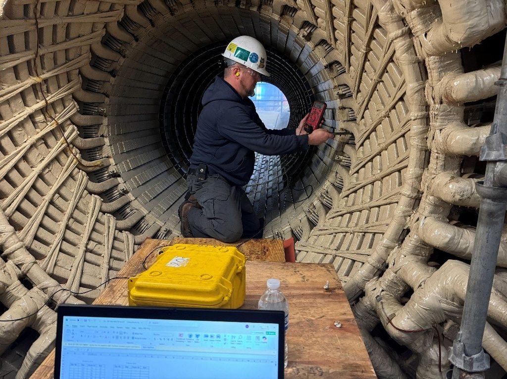
- Handheld capacitance wand or probe (a small electrode pad)
- Precision capacitance meter that reads down to pico-farads
Procedure overview:
- Drain and dry the stator windings as thoroughly as possible, typically using a HIT skid or equivalent.
- Isolate the winding and ground one end of each phase.
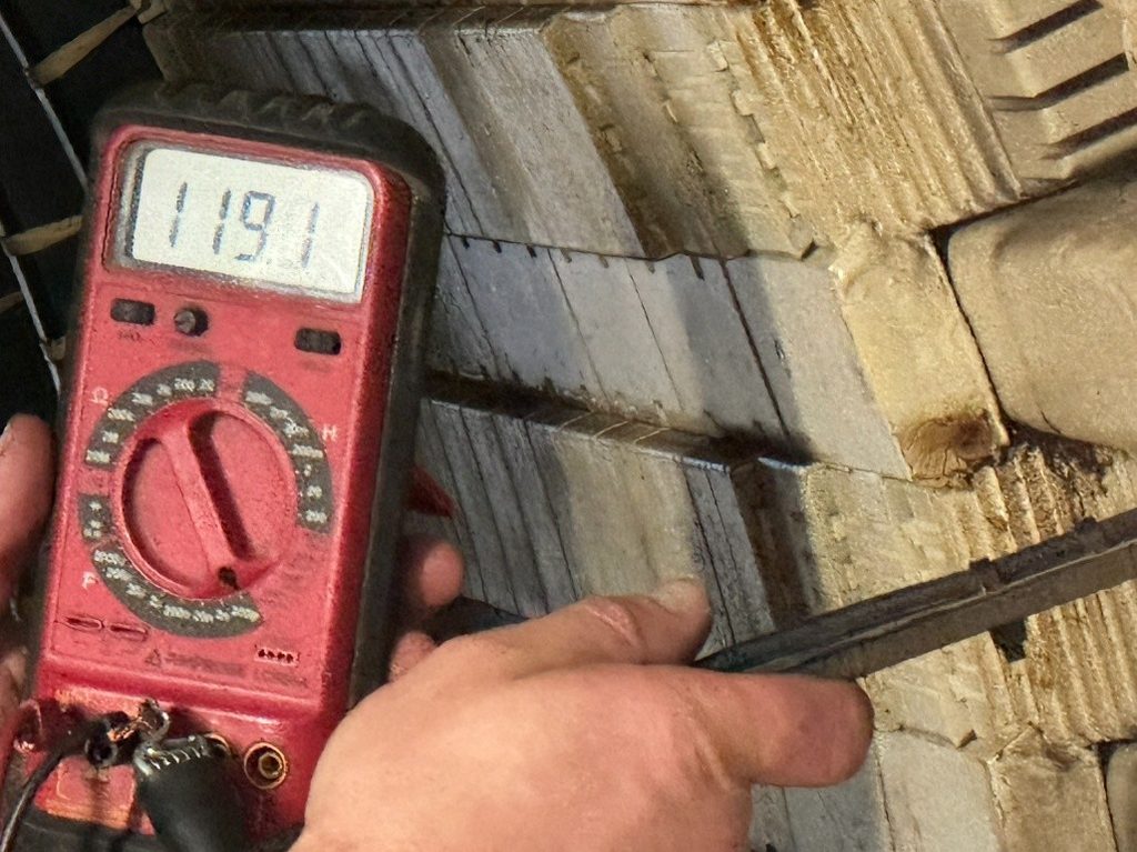
- Press the probe firmly and consistently against the semi-conductive coating on each stator bar inside the first bend at the slot exit.
- Measure capacitance at the same point on every bar.
- Measure the background or stray capacitance by holding the wand in the center of the stator bore every 5–6 slots, and record it.
- Record the values to create a complete “capacitance map” of the entire stator winding.
Interpreting the Results
Comparing each bar against the machine baseline and against its neighbors separates healthy bars from suspect ones.
Healthy (dry) bars:
- Capacitance values are low and consistent along the bar.
- All bars fall within a tight range around the machine-specific baseline.
Wet or leaking bars:
- Capacitance is noticeably higher due to the large increase in εᵣ.
- A bar reading three or more standard deviations above the machine average of all bars is considered a suspect “wet” bar.
- A bar reading significantly above average (thresholds are machine-specific per OEM guidance) usually requires bar replacement.
- Perform visual inspections for any evidence of leakage, such as greenish copper-oxide stains or signs of weeping.
Practical tips:
- Look for both absolute increases and localized hot spots along a single bar.
- Trending data from previous outages is extremely valuable — a bar whose capacitance is steadily rising is degrading. Capturing these readings in a predictive maintenance and condition monitoring program makes the trend easy to track.
Place a Generex Technical Field Advisor on-site to oversee work, guide technicians, and protect your interests.
Need Maintenance Direction
and Support?
Recommended Actions
The capacitance map points directly to the right next step for each bar:
- Good results: return to service and retest in 3–5 years.
- Marginal bars: re-dry, retest, and monitor closely.
- Bad bars: replace the affected bar(s) to prevent in-service failure. Confirm findings with complementary stator diagnostics such as a stator tube resistance test and partial discharge testing.
Summary & Conclusions
Capacitance mapping remains one of the most effective and widely used diagnostic tools for water-cooled generators because it directly measures the physical consequence of water ingress through the change in dielectric properties. A small amount of water produces a large, easily measured rise in bar-to-ground capacitance, which lets testers locate wet bars long before they fail in service. For acceptance thresholds and bar-replacement criteria, refer to OEM documentation and the applicable industry standards.

About the Author
Charles J. Wolfe is the Founder and Principal Engineer of Generex Consulting, with over 30 years of global experience in power generation. He is a recognized expert in generator and excitation systems, trusted by clients worldwide for solving complex engineering challenges.