Flux Probe Test for Generator Rotors: Detect Shorted Turns
Introduction
The rotor (field) winding of a large utility generator is subject to extreme centrifugal forces, thermal cycling, and vibration, which can cause inter-turn insulation failures. These shorts reduce the effective ampere-turns in the affected pole, leading to unbalanced magnetic pull, increased vibration, higher field current demand, and potential loss of excitation.
The flux probe test for generator rotors (also known as the air-gap flux probe test or rotor flux probe test) is a highly effective diagnostic that detects these hidden inter-turn faults by measuring the magnetic flux density profile in the air gap as the rotor rotates. It is performed both online (while the generator is running) and offline, providing direct insight into rotor winding health without requiring rotor removal.
Because the test can be performed at full operating conditions rather than at outage standstill conditions, the flux probe is considered the ultimate authority for detecting shorted turns and estimating their location in the rotor winding.
Background
The flux probe method was developed in the 1970s and has evolved into a practical, widely used rotor condition monitoring technique. Modern flux probe systems are available from specialized providers such as GENERATORTECH and are routinely installed as permanent monitoring equipment on many large generators.
Theory of Operation
How the Probe Generates a Signal
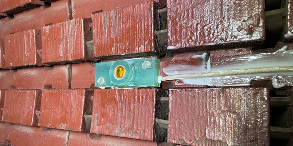
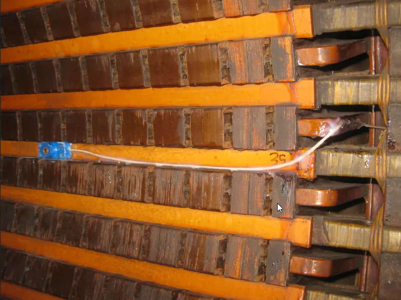
The flux probe is a small, multi-turn search coil mounted in the stator bore, facing the rotor air gap. As the rotor spins, each pole passes the probe and induces a voltage in the coil according to Faraday’s law of electromagnetic induction:
e = −N (dΦ / dt)
Here, N is the number of turns in the probe and Φ (phi) is the magnetic flux linking the coil. The output voltage waveform is therefore proportional to the rate of change of air-gap flux density as each pole passes the probe.
What a Shorted Turn Looks Like in the Waveform
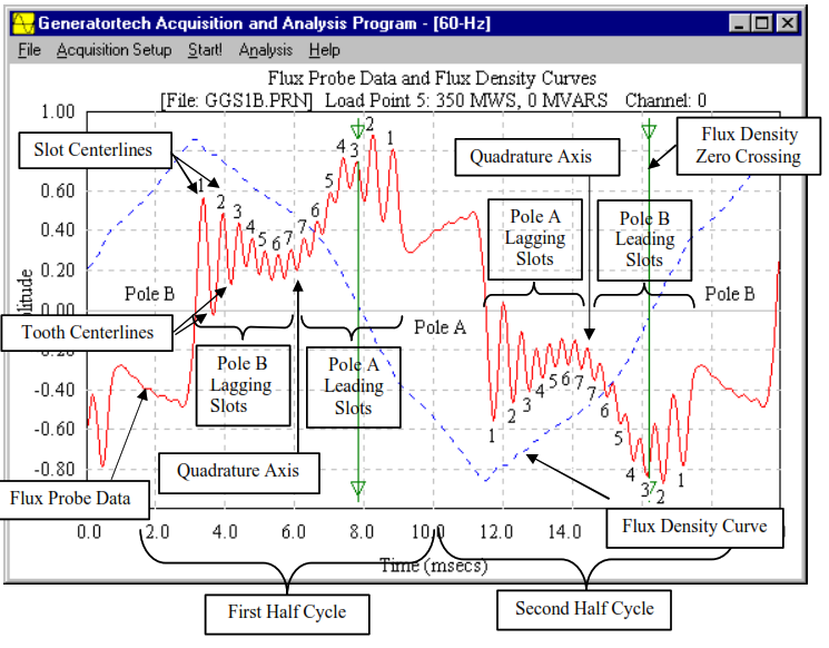
In a healthy rotor, every pole produces an identical flux peak, resulting in a smooth, symmetric waveform with equal peak amplitudes. When one or more turns in a pole are shorted, the effective ampere-turns in that pole are reduced. This causes a localized decrease in magnetic flux density under the affected pole, which appears as a distinct dip, notch, or flattened section in the flux waveform.
The electrical theory is straightforward. The shorted turns create a circulating current that opposes the main field (Lenz’s law), reducing the net flux produced by that pole. The magnitude and position of the dip directly correlate with the number and location of shorted turns.
Test Procedure
The flux probe test can be performed online or offline. It is also quick, typically taking 15 to 30 minutes once the probe is connected.
Online Test Procedure
The online procedure is preferred for continuous monitoring.
- Preparation: Verify that a permanent flux probe is installed in the air gap, usually at the top or side of the stator bore.
- Data Acquisition: With the generator running at synchronous speed (full speed, no-load or loaded), connect the probe output to a high-resolution oscilloscope, digital recorder, or automatic data logger.
- Waveform Capture: Record the flux waveform over several revolutions. Trigger on rotor position (using a keyphasor or once-per-revolution marker) for consistent pole alignment.
- Documentation: Capture and store the waveforms. Modern systems with internet-connected data loggers allow continuous remote monitoring and automatic alerting.
Offline Test Procedure
When the unit is shut down, the rotor is turned at low speed (or manually indexed at standstill) while the same waveform capture is performed.
Interpreting Flux Probe Test Results
Healthy Rotor
All poles produce identical, symmetrical flux peaks with no visible dips or notches.
Marginal Results
Small, repeatable dips (less than a 5–10% reduction in peak flux) on one pole are considered marginal. Monitor these closely.
Faulty Rotor
A clear, repeatable notch or dip in the waveform corresponding to one or more poles indicates a fault. The depth of the dip indicates the number of shorted turns, and the angular position identifies which pole is affected. Multiple dips may indicate shorts on several poles.
Need Expert
Engineering Guidance?
Get independent technical advisory for your power generation project, from design review to project oversight.
Trending Results Over Time
Trending is essential. Increasing dip depth, or new dips on successive tests, confirms progressive inter-turn degradation. Results are often expressed as percent flux reduction per pole relative to the average healthy pole. Remote monitoring systems can automatically flag deviations for immediate review.
Correlating these trends with turbine generator vibration monitoring and analysis can further confirm that a developing shorted-turn condition is affecting rotor behavior.
Repair Scenarios
If the test results indicate a fault, the repair approach depends on the severity of the shorts.
Minor Shorts
A small dip, with one or two turns affected, can often be addressed by inspecting accessible areas, cleaning contamination, or applying insulating varnish. Re-test after the repair.
Moderate Shorts
A clear dip with several shorted turns calls for locating the exact coil using complementary tests, such as pole drop, RSO, or an AC impedance test. The affected coil or turns are then repaired or replaced.
Severe or Widespread Shorts
Large dips on multiple poles usually require a full rotor rewind or complete pole-coil replacement.
Post-Repair Verification
All repairs must be followed by a repeat flux probe test, plus RSO, pole drop, and a 500 V Megger polarization index test, to confirm that the fault has been eliminated before the rotor is returned to service.
IEEE and ANSI Documentation
Flux probe testing is described in IEEE Std 115-2019, IEEE Guide for Test Procedures for Synchronous Machines, under rotor inter-turn fault detection techniques. Supporting guidance appears in IEEE Std 56-2016, IEEE Guide for Insulation Maintenance of Electric Machines.
While no standalone ANSI/IEEE standard is dedicated exclusively to flux probe testing, IEEE 115 is the primary reference and is frequently dual-designated as ANSI/IEEE. OEM technical information letters and EPRI reports provide machine-specific installation details and acceptance criteria.
Summary and Conclusions
The flux probe test for generator rotors is a powerful, non-invasive diagnostic that detects inter-turn shorts in large utility generator rotors by directly measuring distortions in the air-gap flux profile as the rotor rotates. The electrical theory is based on Faraday’s law: any reduction in ampere-turns caused by shorted turns produces a measurable dip in the induced voltage waveform.
Modern systems often include automatic data loggers that can connect to the internet for continuous remote monitoring and real-time alerts. Whether performed online at full speed or offline, the test provides clear, repeatable evidence of rotor winding health. When performed and interpreted according to IEEE 115, it enables early, targeted repairs that prevent vibration, unbalanced magnetic pull, increased field current, and catastrophic rotor failure.
As generator fleets age and operate under higher cyclic duty, routine flux probe testing has become an essential part of modern predictive maintenance programs, delivering high diagnostic value with minimal downtime.

About the Author
Charles J. Wolfe is the Founder and Principal Engineer of Generex Consulting, with over 30 years of global experience in power generation. He is a recognized expert in generator and excitation systems, trusted by clients worldwide for solving complex engineering challenges.