Generator Protection Relays: Settings & Maintenance Guide
Introduction
Generator protection relays are the critical intelligence layer safeguarding large utility turbine-driven synchronous generators against internal faults, external system disturbances, and abnormal operating conditions. In machines rated 100 MW and above, a single undetected fault or mis-operation can cause catastrophic damage to the stator, rotor, or prime mover — leading to extended outages that cost millions in lost generation and repair.
Modern multifunction digital relays integrate dozens of protective elements, but correct application, settings, and response to abnormal conditions remain essential for reliability. For consulting firms specializing in generator testing, inspection, and repair, expertise in protection relay performance directly supports outage planning, root-cause analysis, and life-extension strategies. This article provides a practical overview of key protection functions, setting considerations, maintenance procedures, and response to abnormal operations in utility-scale applications.
Background: The Role of Protection in Large Generators
Large turbine-driven generators operate under high mechanical, thermal, and electrical stresses while interconnected to the bulk power system. Protection systems must rapidly detect internal faults — such as stator phase or ground faults — while remaining secure against external faults and normal transients such as synchronizing or load changes.
Historically, discrete electromechanical or static relays were used; today, digital multifunction relays dominate, offering self-diagnostics, event recording, and communication capabilities. However, improper settings or failure to address abnormal conditions — such as loss of field, reverse power, or off-frequency operation — continue to cause unnecessary trips or delayed fault clearing. Effective protection balances sensitivity, selectivity, and speed while complying with NERC reliability standards and grid code requirements.
Theory of Operation
Generator protection relays monitor voltages, currents, frequency, and other parameters through instrument transformers (CTs and PTs) to detect deviations from normal operation. Core principles include differential protection for internal faults (87G), impedance-based elements for backup, and specialized functions for abnormal conditions.
Key Protective Elements (ANSI/IEEE Device Numbers)
- 87G — Generator differential for phase faults.
- 40 — Loss-of-field (impedance or reactive power).
- 32 — Reverse power (anti-motoring).
- 46 — Negative-sequence (unbalanced currents).
- 24 — Volts-per-hertz (overexcitation).
- 81 — Under/overfrequency.
- 59 / 27 — Over/undervoltage.
- 21 / 51V — Distance or voltage-restrained overcurrent for system backup.
- 64F / 27TN / 59N — Field ground and 100% stator ground.
- 78 — Out-of-step / loss of synchronism.
How Settings Are Coordinated
During normal operation, the relay remains secure. Upon detecting an abnormal condition — for example, field current collapse causing loss of field — the relay compares the measured quantity against predefined pickup and time-delay settings, then issues a trip or alarm. Settings must coordinate with the generator’s capability curve, the excitation system (brushless or static), and turbine limits, while accounting for CT saturation, transient DC offset, and harmonic content.
management.
Why Did Your Unit
Suddenly Trip?
Our engineers identify the true root cause of equipment failures, and help prevent future events
Maintenance Procedures
Routine maintenance of generator protection relays ensures reliability and prevents hidden failures.
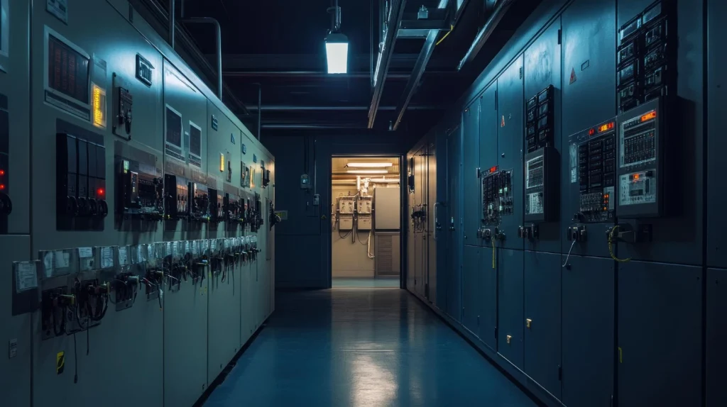
1. Visual and Physical Inspection — Check relay panels, wiring, grounding, and connections for corrosion, loose terminals, or overheating. Verify auxiliary power supplies and battery backup.
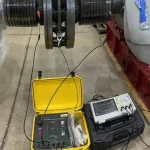
2. Functional Testing — Perform secondary injection testing of all enabled elements using relay-specific test sets. Verify pickup, timing, and logic — including breaker failure, lockout relays (86), and trip coil supervision.
3. Settings Verification — Download and compare relay settings against the approved coordination study. Check for firmware updates and configuration drift.
4. Event Record and Self-Diagnostic Review — Analyze oscillography, sequence-of-events data, and self-test alarms from the relay historian.
5. Instrument Transformer Checks — Test CT and PT ratios, polarity, and burden; inspect for saturation or insulation degradation.
6. End-to-End Testing — Simulate abnormal conditions such as loss of field or reverse power to confirm overall scheme performance, including AVR and turbine control interaction.
Recommended frequency: every 2–4 years, or after major system events. Digital relays operating in cycling duty warrant more frequent checks.
Repair Scenarios
Repair scope depends on inspection and test results.
Minor (1–2 days)
Loose wiring, minor configuration errors, or failed auxiliary relays — corrected on-site and re-tested.
Moderate (3–7 days)
Faulty I/O modules, outdated firmware, or drifted settings requiring recalibration — resolved through module replacement and full functional verification.
Major (1–3 weeks)
Complete relay failure, obsolete hardware, or widespread miscoordination — full replacement with a modern multifunction digital relay, including new settings development, wiring modifications, and commissioning.
Upgrades often incorporate improved algorithms (such as CT saturation detection) and better integration with plant SCADA or DCS. Post-repair testing must confirm coordination with adjacent protection and compliance with grid requirements.
Common Issues and Remedies
The most frequent problems seen with generator protection relays include nuisance tripping during external faults or transients, failure to detect evolving faults, and incorrect response to abnormal conditions.
CT Saturation or Inaccurate Settings
Causes false differential (87G) operation or delayed backup protection. Remedy: increase slope or add time delay; use relays with saturation detection.
Loss of Field (40)
Often mis-set, leading to pole slipping or unnecessary trips. Remedy: verify impedance characteristics against machine capability curves.
Reverse Power (32)
Trips during synchronization or light-load conditions if set too sensitively. Remedy: apply an appropriate time delay (typically 10–30 seconds) and coordinate with turbine minimum-power limits.
Volts-per-Hertz (24)
Overexcitation during startup or load rejection. Remedy: coordinate settings with AVR limiters and turbine capability. Regular AVR inspection and maintenance helps ensure the excitation side of this coordination remains reliable.
Abnormal Frequency (81)
Off-frequency operation can damage turbine blades or cause thermal stress. Remedy: set multi-stage under/overfrequency elements with time delays matching manufacturer limits — for example, steam turbines tolerate only limited time at 57–63 Hz.
Stator Ground Faults
High-impedance faults may go undetected. Remedy: implement 100% stator ground schemes using 27TN + 59N or third-harmonic methods.
Other recurring issues include blown VT fuses (detected by 60), inadvertent energization (50/27), and out-of-step conditions (78). Remedies generally involve updated coordination studies, improved settings, and periodic testing.
IEEE and ANSI Documentation
IEEE Std C37.102 (Guide for AC Generator Protection) is the primary reference, providing application guidance for large hydraulic, steam, and combustion-turbine generators against internal faults and abnormal conditions. Supporting standards include IEEE C37.101 (Guide for Generator Ground Protection) and IEEE C37.106 (Guide for Abnormal Frequency Protection for Power Generating Plants).
IEEE device numbers (ANSI C37.2) standardize function identification — for example, 87G for generator differential and 40 for loss of field. Additional resources include the IEEE Tutorial on the Protection of Synchronous Generators (PSRC) and IEEE Std 115 for synchronous machine testing.
Thorough documentation — settings files, test results, event reports, as-found/as-left data, and coordination studies — is mandatory for NERC compliance (for example, the PRC standards), insurance audits, and effective root-cause analysis after events.
Summary and Conclusions
Generator protection relays, when properly applied, set, and maintained, form the backbone of safe and reliable operation for large utility turbine-driven generators. By addressing both internal faults and abnormal conditions — loss of field, reverse power, overexcitation, unbalanced currents, and off-frequency events — protection systems prevent costly damage while minimizing unnecessary trips.
Adherence to IEEE C37.102 and related standards, combined with rigorous maintenance procedures, functional testing, and detailed documentation, ensures coordination, security, and dependability. For utilities facing aging fleets, increased cycling, and stricter grid requirements, expert evaluation of protection schemes delivers substantial value through reduced outage risk, faster fault clearing, and extended generator life. Investing in specialized testing, inspection, and repair services for generator protection relays is a proactive strategy that supports overall plant reliability and long-term asset

About the Author
Charles J. Wolfe is the Founder and Principal Engineer of Generex Consulting, with over 30 years of global experience in power generation. He is a recognized expert in generator and excitation systems, trusted by clients worldwide for solving complex engineering challenges.