Brushless vs. Static Excitation: O&M Comparison
Introduction
Excitation systems supply direct current to the rotor (field) winding of large, utility-scale, turbine-driven synchronous generators to establish the rotating magnetic field necessary for voltage generation. Two dominant types in modern utility applications are brushless excitation systems (typically AC alternator-rectifier designs with rotating diodes) and static excitation systems (thyristor- or IGBT-based rectifiers supplied from the generator terminals or auxiliary sources via slip rings and brushes). Brushless systems eliminate carbon brushes and slip rings, reducing certain maintenance burdens, while static systems offer superior dynamic response and forcing capability. Selection depends on generator size, grid-stability requirements, maintenance philosophy, and operational duty (base-load vs. cycling). For power generation consulting firms that specialize in generator testing, inspection, and repair, a clear understanding of these systems enables optimized outage planning, early fault detection, and cost-effective life-extension decisions for aging fleets.
How Brushless and Static Excitation Systems Work
Both systems regulate generator terminal voltage through a closed-loop automatic voltage regulator (AVR) that compares sensed voltage to a setpoint and adjusts field current. In a brushless excitation system, a shaft-mounted AC exciter alternator (driven at synchronous speed) generates AC power. Rotating rectifiers (diodes) mounted on the rotor convert this AC to DC, which feeds the main generator field directly—eliminating brushes and slip rings for the main field. The AVR controls the exciter field, often via a small pilot exciter or permanent-magnet generator for black-start capability. Response time is limited by the exciter’s time constant and rotating mass, resulting in moderate ceiling voltage and slower initial response compared with static systems.
In a static excitation system, power is derived from the generator terminals (potential source) or from a combination of voltage and current (compound source). Thyristor bridges—or IGBT converters in modern designs—provide controlled rectification directly to the main field through slip rings and brushes. The AVR modulates firing angles for rapid, precise control. Static systems achieve high initial response (ceiling voltages often two to three times rated) and excellent negative field forcing for fast de-excitation during load rejection or faults. However, they require brushes and slip rings to transfer power to the rotating field.
Modern digital AVRs in both systems incorporate PID control, power system stabilizers (PSS), overexcitation limiters (OEL), underexcitation limiters (UEL), and volts-per-hertz protection. Static systems generally provide faster transient response and better damping in large, grid-connected units, while brushless systems prioritize simplicity and reduced carbon-dust generation.
Why a Side-by-Side Comparison Matters
Comparing brushless and static excitation systems is essential for utilities managing large turbine-driven generators. Brushless designs minimize certain mechanical wear but may compromise dynamic performance in demanding grid environments. Static systems deliver superior response and stability margins but introduce brush and slip-ring maintenance. Effective inspection and maintenance programs must address the unique characteristics of each type to prevent voltage instability, rotor overheating, or forced outages. This article provides a practical, side-by-side comparison of operation and maintenance—including procedures, common issues, repair approaches, and industry standards—to support informed decision-making for testing, inspection, and repair services.
Maintenance Procedures
Maintenance procedures differ significantly because of the underlying system architecture.
Brushless Excitation System Maintenance
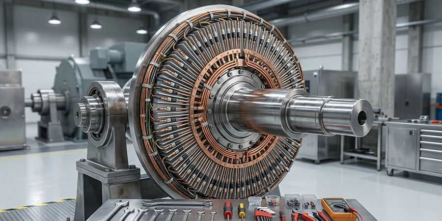
- Inspect the rotating exciter, diode wheel, fuses, and connections during outages (with the rotor removed or via access ports). Use strobe lights for visual diode and fuse checks while the unit is on turning gear.
- Perform insulation resistance (IR) and polarization index (PI) tests on the exciter windings and main field.
- Check diode redundancy and replace failed diodes or fuses (typically offline).
- Inspect exciter bearings, air filters, and cooling paths for contamination.
- Test AVR functionality, tuning, and limiters offline.
- Trend field-current and voltage data to catch early diode or winding degradation.
Static Excitation System Maintenance
- Focus on brushes, slip rings, and collector maintenance—inspect for wear, grooving, or uneven film, and polish or replace as needed.
- Clean and test thyristor/IGBT bridges, snubbers, and fuses (redundant banks often allow online replacement).
- Verify cooling fans, heat sinks, and power supplies.
- Perform functional tests on the AVR, PSS, and limiters, including step-response and protective-function verification.
- Monitor carbon-dust accumulation and grounding brushes.
Both systems require AVR calibration, configuration backup (for digital units), and integration with generator protection. Maintenance intervals of every two to four years—or after significant grid events—are recommended, with brushless systems generally requiring less frequent brush-related work.
Test, inspect, and troubleshoot static and brushless excitation systems to keep your unit running reliably.
Excitation System Issues?
Common Issues and Remedies
Although brushless and static systems perform the same function, their failure modes are shaped by very different hardware. Brushless faults tend to originate on the rotating assembly, where components are difficult to inspect while the unit is running, so problems often surface only during outages or after a trip. Static faults, by contrast, concentrate on the wear items that live in the accessible collector and power-electronics compartments, making them easier to catch early with routine walkdowns. Recognizing these distinct patterns—and matching each to the right remedy—is the key to preventing voltage instability, rotor overheating, and avoidable forced outages.
Brushless System Issues and Fixes
Brushless systems commonly experience rotating diode or fuse failures (from thermal or mechanical stress and contamination), exciter winding degradation, and diode-wheel contamination that can lead to flashover. Slower response can also reduce stability margins during severe grid disturbances. Remedies include diode replacement with upgraded redundancy, improved sealing against contaminants, and exciter rewinding or refurbishment.
Static System Issues and Fixes
Static systems frequently encounter brush and slip-ring wear, carbon-dust buildup (which can cause tracking or grounding issues), thyristor failures, and overheating of power electronics. Faster response is an advantage, but poor brush maintenance can lead to voltage instability or field-flashing problems. Remedies include regular brush replacement, slip-ring resurfacing, improved ventilation, and thyristor-module swaps (often possible online when redundancy is available).
In both systems, AVR tuning drift, limiter malfunctions, and power-supply failures can occur. Digital upgrades often resolve obsolescence and improve diagnostics for either type.
Repair Scenarios
Repair scope varies by system and severity:
- Minor (both types): Cleaning, brush and slip-ring maintenance (static), diode and fuse replacement (brushless), and AVR recalibration—typically one to three days during short outages.
- Moderate: Thyristor/IGBT bridge repair or partial replacement (static), exciter winding touch-up or diode-wheel refurbishment (brushless), and AVR module replacement—three to seven days.
- Major: Full exciter rotor refurbishment or replacement (brushless), or a complete static converter upgrade or full excitation-system replacement with modern digital controls—one to four weeks, including commissioning and tuning.
Static-to-brushless conversions (or vice versa) are major projects that require rotor modifications. Upgrading either system to a modern digital AVR with enhanced PSS and limiters often yields the best long-term reliability gains without a full system replacement.
IEEE and ANSI Documentation
IEEE standards provide critical guidance for both excitation system types. IEEE Std 421.1 offers definitions and terminology for excitation systems, including brushless (alternator-rectifier with rotating rectifiers) and static (potential- or compound-source controlled rectifiers). IEEE Std 421.2 addresses the identification, testing, and evaluation of dynamic performance. IEEE Std 421.5 presents recommended models (Type AC for brushless, Type ST for static) for power-system stability studies, including limiters and PSS. IEEE Std 421.4 guides specification preparation. Related documents include IEEE C50.13 for cylindrical-rotor generators and IEEE Std 115 for synchronous-machine testing. Thorough documentation—recording as-found and as-left test data, AVR settings, trend plots, photographs, and maintenance history—ensures NERC compliance, supports root-cause analysis, and facilitates life assessment.
Summary and Conclusions
Brushless and static excitation systems each offer distinct trade-offs for large, utility-scale turbine-driven generators. Brushless systems provide lower maintenance through the elimination of brushes and slip rings, reduced carbon dust, and simpler mechanical design, making them attractive for reliability-focused operations. Static systems deliver faster response times, higher ceiling voltages, superior dynamic performance, and more effective power-system stabilization—advantages that are particularly valuable for large units on strong grids or under cycling duty.
Maintenance for brushless systems centers on rotating components (diodes, fuses, and exciter windings), while static systems require diligent brush, slip-ring, and power-electronics care. Common issues—diode failures in brushless units versus brush wear in static units—can be mitigated through proactive inspection, testing, and timely repairs. Adherence to the IEEE Std 421 series, combined with detailed documentation and periodic functional testing, maximizes availability and supports regulatory compliance.
For utilities and plant operators, a tailored inspection and maintenance program that leverages the strengths of each system type delivers significant value. Expert consulting services in testing, inspection, and repair help optimize excitation performance, extend equipment life, reduce outage durations, and enhance overall generator reliability in today’s demanding grid environment.

About the Author
Charles J. Wolfe is the Founder and Principal Engineer of Generex Consulting, with over 30 years of global experience in power generation. He is a recognized expert in generator and excitation systems, trusted by clients worldwide for solving complex engineering challenges.