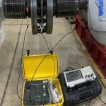
Generator Rotor Pole Drop Test: Procedure & Interpretation
Introduction
The rotor (field) winding of a large utility generator consists of multiple poles connected in series. Inter-turn shorts can develop from insulation abrasion under centrifugal force, thermal cycling, vibration, or contamination. These shorts may not appear in DC resistance or insulation resistance (Megger) tests because the fault can be voltage-dependent or intermittent.
The Pole Drop Test, also called the Inter-Pole Voltage Drop Test or Pole-to-Pole Drop Test, is a simple, low-voltage, offline DC diagnostic that detects these hidden turn-to-turn faults by comparing voltage drops across individual poles or coils. It is a standard tool for commissioning, routine outages, post-repair verification, and root-cause investigations on both salient-pole and round-rotor machines.
Background and History
Pole drop testing has been used since the 1950s and 1960s, as generators grew larger and rotor insulation failures became a leading cause of unplanned outages. Early methods relied on visual inspection and resistance measurements, which often missed intermittent or low-resistance shorts.
The test gained popularity because it is fast, requires only basic equipment, and can be performed with the rotor in place. It is especially valuable for machines showing abnormal vibration, unbalanced magnetic pull, or elevated field current. Today it is performed alongside the AC impedance test and Megger/polarization index test as part of a complete rotor diagnostic suite.
Theory of Operation
The rotor field winding can be modeled as a series of coils, each with inductance (L) and resistance (R). When a low DC current (I), typically 1–5% of the rated field current, is injected across the entire winding, the voltage drop across each healthy pole is:
V_pole = I × (R + small inductive effects during current ramp)
In a healthy rotor, voltage drops are nearly equal across all poles, typically within 2–5%. An inter-turn short effectively reduces the number of turns in that pole, lowering its inductance and resistance. This causes a measurable reduction in voltage drop across the affected pole, because less voltage is required to push the same current through the shortened circuit.
The electrical theory is governed by Ohm’s law and the reduction in effective turns:
V_shorted pole = I × R_effective, where R_effective < R_healthy
The test uses DC to eliminate inductive reactance effects, making the measurement purely resistive and proportional to the number of effective turns. A sudden drop in voltage across one pole reveals the location and severity of the short.
Test Procedure
The pole drop test is performed offline with the rotor stationary, either in place or removed for bench testing. The five steps below cover the full workflow from lockout through discharge. Complete testing typically takes 30 to 60 minutes.
- Preparation: Disconnect and isolate the rotor field leads. Ground the shaft. Clean the slip rings if accessible. Ensure the rotor is at ambient temperature.
- Test setup: Connect a low-voltage DC power supply (typically 10–50 V) or a constant-current source across the field terminals. Use a calibrated digital voltmeter or millivoltmeter with leads that can reach each pole connection.
- Measurement: Inject a low DC current (1–5% of the rated field current). Measure and record the voltage drop across each individual pole (pole-to-pole) or each coil group while the current is stable.
- Repeatability check: Take multiple readings at slightly different current levels to confirm repeatability and rule out contact resistance at the test leads.
- Safety and discharge: Discharge the winding after testing and follow lock-out / tag-out procedures throughout the job.
Interpreting the Results
Results are evaluated by comparing voltage drops between poles, both against each other and against baseline data from prior outages. The categories below reflect common industry practice; always check the OEM manual for machine-specific tolerances.
Healthy Rotor
Voltage drops are within 2–5% of each other across all poles (OEM-specific tolerance).
Marginal Rotor
A 5–10% variation between poles indicates early or developing turn-to-turn insulation weakness. Monitor closely on the next outage and trend against baseline.
Faulty Rotor
Greater than 10% lower voltage drop across one or more poles (or coils) indicates inter-turn shorts. The greater the drop, the more turns are shorted.
Trending is critical: a progressive reduction in voltage drop on the same pole over successive tests signals worsening shorts. Results are often plotted as a bar chart or tabulated for easy comparison with baseline data.
Need Maintenance Direction
and Support?
Place a Generex Technical Field Advisor on-site to oversee work, guide technicians, and protect your interests.
Repair Scenarios Based on Results
The corrective action depends on how many poles are affected and how much the voltage drop deviates from healthy readings. The three scenarios below cover the typical repair paths, from a light in-place cleanup to a full rotor rewind.
Minor Shorts
Small voltage drop difference on a single pole. Inspect accessible areas, clean any contamination, or apply insulating varnish. Re-test after the repair to confirm the drop has returned to baseline.
Moderate Shorts
A clear pole drop with multiple turns affected. Locate the exact shorted coil using further pole-drop subdivision or surge testing, then repair or replace the affected coil or turns.
Severe or Widespread Shorts
A large voltage drop on multiple poles usually points to a full rotor rewind or complete pole-coil replacement.
All repairs must be followed by a repeat pole drop test, along with a 500 V Megger / polarization index test on the rotor and an AC impedance test, to confirm the fault has been eliminated before the rotor is returned to service.
IEEE and ANSI Documentation
The pole drop test is described in IEEE Std 115-2019, IEEE Guide for Test Procedures for Synchronous Machines, which includes methods for detecting rotor inter-turn faults. Supporting guidance appears in IEEE Std 56-2016, IEEE Guide for Insulation Maintenance of Electric Machines.
While no standalone ANSI/IEEE standard is dedicated exclusively to the pole drop test, IEEE 115 is the primary reference and is frequently dual-designated as ANSI/IEEE. OEM technical information letters and EPRI reports provide machine-specific current levels and acceptance tolerances.
Summary and Conclusions
The pole drop test is a fast, low-cost, and highly effective offline diagnostic for detecting inter-turn shorts in large utility generator rotors. By applying a low DC current and measuring the voltage drop across each pole, technicians can quickly identify poles with reduced effective turns caused by shorted insulation.
The electrical theory is straightforward: shorts lower the resistance and inductance of the affected pole, producing a measurable voltage drop that is easily compared to healthy poles. When performed and interpreted according to IEEE 115, the test enables targeted repairs that prevent unbalanced magnetic forces, vibration, loss of excitation, and costly rotor rewinds.
As generator fleets age and operate under higher cyclic duty, routine pole drop testing remains an indispensable part of modern predictive maintenance programs, delivering reliable results with minimal equipment and downtime.

About the Author
Charles J. Wolfe is the Founder and Principal Engineer of Generex Consulting, with over 30 years of global experience in power generation. He is a recognized expert in generator and excitation systems, trusted by clients worldwide for solving complex engineering challenges.