Stator Phase Resistance Test: DC Winding Resistance Guide
Introduction
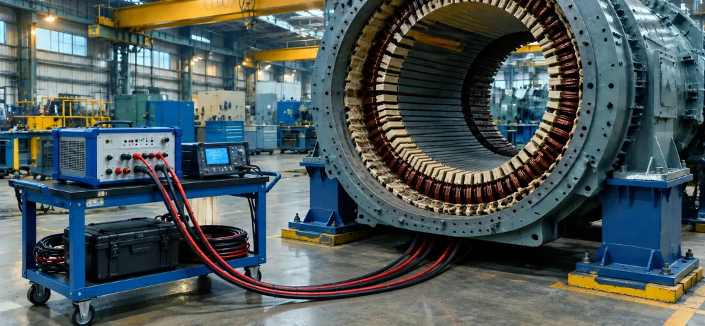
The stator phase resistance test (also called the DC winding resistance test) is a simple, low-voltage, offline diagnostic performed on the three-phase stator winding during planned outages. It measures the DC resistance of each complete phase (A, B, and C) from the main lead to the neutral connection.
Test Motivation
Stator phase resistance testing is done to verify the electrical integrity of the entire winding circuit. Problems that can develop over time include:
- High-resistance brazed joints or connections
- Broken or open strands inside Roebel bars
- Loose or corroded main lead and neutral connections
- Manufacturing defects or damage from previous faults
Any of these issues can create imbalance between phases, increased I²R (ohmic) heating, and reduced efficiency. Early detection prevents hot spots, insulation degradation, and eventual winding failure.
The test is especially important after a rewind or major repair, or when other tests (a Megger polarization index test, a DC hipot test, or a transposition test) show anomalies. It provides a quick, quantitative check that other tests cannot replace.
Test Theory
Ohm’s Law and Test Equipment
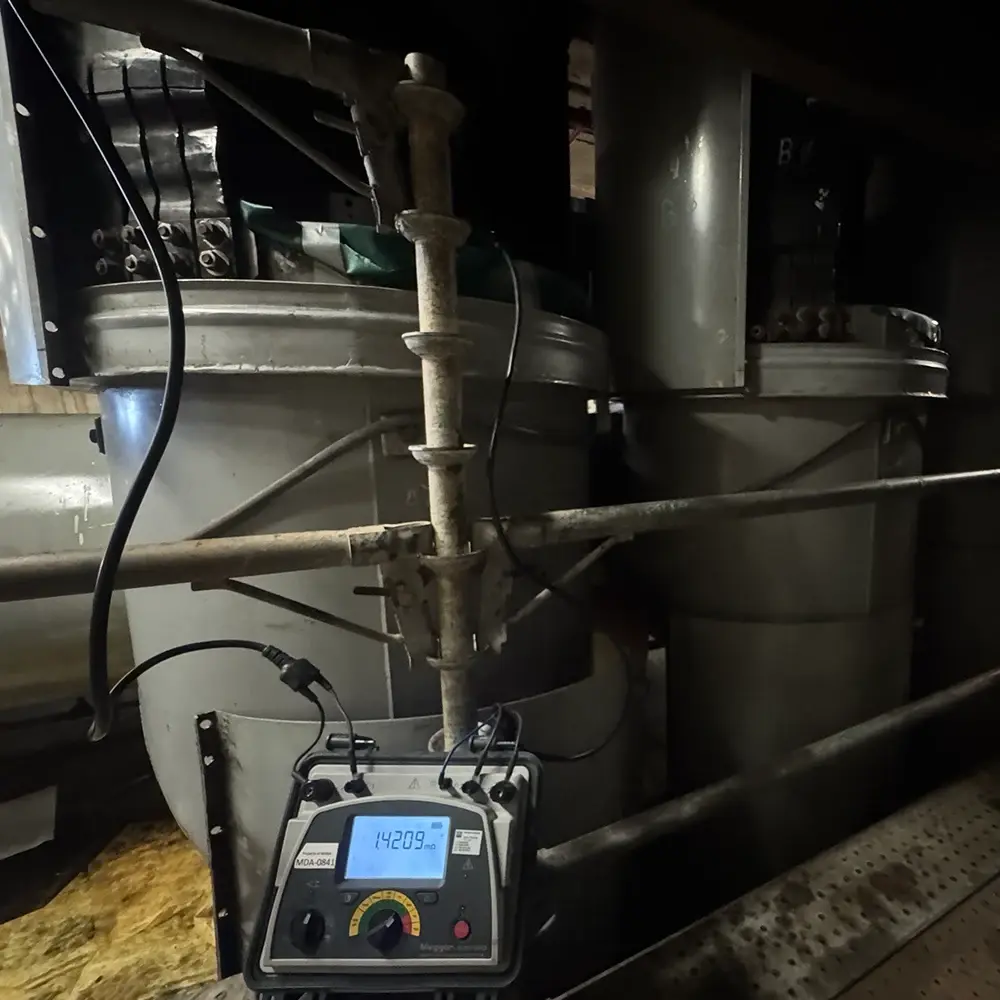
The test is based on Ohm’s law: R = V/I. A low DC voltage is applied across each complete phase winding while the current (typically 10 amps) is measured. A digital low resistance ohmmeter (DLRO) is the most commonly used device. Some engineers occasionally call this test a “ductor” test.
Temperature Correction
The resistance of each phase is calculated and corrected to a standard temperature (usually 25°C) using the following formula:

This formula applies to copper windings, for which the constant is 234.5.
Expected Phase Balance
All three phases should have nearly identical resistance values, within a 1% spread, because they are wound with the same number of turns, the same conductor material, and the same cross-sectional area. Any significant deviation indicates a problem in one or more phases.
Testing Methodology
Prerequisites
- Generator shut down, locked out, and rotor removed or end bells off.
- All phase and neutral leads disconnected and isolated.
Test Procedure
- Use a precision micro-ohmmeter, such as a DLRO, or a low-voltage DC power supply with an ammeter and voltmeter.
- Apply DC current through one complete phase (main lead to neutral).
- Measure voltage and current, then calculate resistance.
- Repeat for phases A, B, and C.
- Record the winding temperature at the time of the test (usually with embedded RTDs).
- Correct all readings to the same reference temperature.
The test is quick and non-destructive.
Interpreting Stator Phase Resistance Test Results
Acceptance Criteria
All three phases must be compared after temperature correction. Typical acceptance criteria (per IEEE and OEMs) are shown below.
| Phase-to-Phase Deviation | Interpretation | Action Required? |
| Less than 0.5% | Excellent: balanced winding | None |
| 0.5% to 2% | Acceptable | Monitor on next outage |
| 2% to 5% | Marginal: possible high-resistance joint or broken strands | Investigate and retest |
| Greater than 5% | Unacceptable: serious problem | Immediate repair required |
Reading the Patterns
A single phase showing significantly higher resistance usually indicates a high-resistance connection or broken strands. If all three phases are high but balanced, the cause may be uniform corrosion or poor brazing. Trending the corrected resistance values over successive outages is very valuable.
Need Maintenance Direction
and Support?
Place a Generex Technical Field Advisor on-site to oversee work, guide technicians, and protect your interests.
What to Do If Results Are Bad
When temperature-corrected readings fall outside the acceptable range, or one phase stands out from the others, follow a structured response rather than going straight to repairs. First rule out test errors, then locate the fault through further investigation, and finally choose a repair that matches its severity. The steps below follow that order.
Immediate Steps
- Verify the test connections and repeat the measurement.
- Check and clean all accessible main lead and neutral connections.
Further Investigation
- Perform a transposition test on the affected phase to check for broken strands.
- Inspect brazed joints and end-winding connections visually or with a borescope.
- Apply 1,000 amps of DC current per square inch of conductor cross-sectional area across the affected phase, allow it to heat for 30 to 60 minutes, and use a thermography camera to survey the windings and connection rings for hot spots.
- See the Case Studies section of this website for a deeper dive into this subject.
Repair Actions
- Re-braze or re-solder high-resistance connections.
- Replace individual stator bars if broken strands are confirmed.
- In severe cases, plan a partial or full stator rewind.
- Re-silverplate any connections where the plating has been compromised.
Never return the generator to service with a phase resistance imbalance greater than 2–3% unless the OEM approves it with documented justification.
Controlling Standards and Documentation
- IEEE Std 115: IEEE Guide for Test Procedures for Synchronous Machines (covers DC resistance measurement of armature windings).
- IEEE Std 43: IEEE Recommended Practice for Testing Insulation Resistance of Electric Machinery (references resistance measurements as part of overall winding evaluation).
- IEEE Std 62.2: IEEE Guide for Diagnostic Field Testing of Electric Power Apparatus—Electrical Machinery (specifically addresses stator winding resistance testing and phase balance).
- ANSI/NETA MTS: Maintenance Testing Specifications for Electrical Power Equipment (lists DC winding resistance testing as a required test for rotating machinery).
Most OEM maintenance manuals (GE, Siemens/Westinghouse, and Mitsubishi) also require this test on every major outage.
Summary and Conclusions
The stator phase resistance test is one of the fastest and most effective ways to confirm that all three phases are electrically balanced and free of high-resistance connections or broken strands. When performed regularly and trended, it can provide early warning of problems that could otherwise lead to costly forced outages.
It is especially valuable after a rewind or major repair, and it complements insulation and transposition testing by verifying the electrical integrity of the winding circuit itself.

About the Author
Charles J. Wolfe is the Founder and Principal Engineer of Generex Consulting, with over 30 years of global experience in power generation. He is a recognized expert in generator and excitation systems, trusted by clients worldwide for solving complex engineering challenges.