Stator Visual Inspection Guide for Generators
Background
Over years of service, the generator stator is subjected to continuous 120 Hz electromagnetic forces, thermal cycling from load changes, and vibration transmitted from the turbine. These forces gradually loosen windings, blocking materials, and core support structures. Visual inspection during scheduled outages, when the rotor is removed, provides the earliest and most direct evidence of developing problems. Industry data consistently shows that the majority of stator failures are preceded by visible mechanical degradation months or years before electrical tests indicate serious issues. For companies specializing in generator testing, inspection, and repair, expert stator visual inspections are a critical service that can prevent catastrophic failures and extend generator life well beyond 40 years.
Principles of Operation
A large turbine-driven generator stator consists of a laminated iron core tightly clamped and keyed to the frame, with form-wound stator bars or coils secured in slots by wedges and supported in the end regions by rings, braces, and ties. Electromagnetic forces act on the current-carrying conductors at twice line frequency (120 Hz on 60 Hz systems), while the rotating magnetic field from the rotor adds further vibratory stresses. Hydrogen cooling gas circulates at pressure to remove heat, but any migration of turbine lube oil into the generator creates a reactive environment. Continuous mechanical agitation from vibration, combined with hydrogen, alters the oil’s properties and produces characteristic wear patterns on loose components. In air-cooled machines, high local electric fields can also trigger ionization, and in older machines, historical coatings and sealants can degrade into chemical contaminants. These mechanisms — vibration-induced looseness, oil contamination, fretting wear, electrical stress, and chemical degradation — manifest visibly as greasing, dusting, red dusting, corona discharge, or lead carbonate contamination, providing clear early-warning signs of mechanical, electrical, or chemical distress.
Introduction
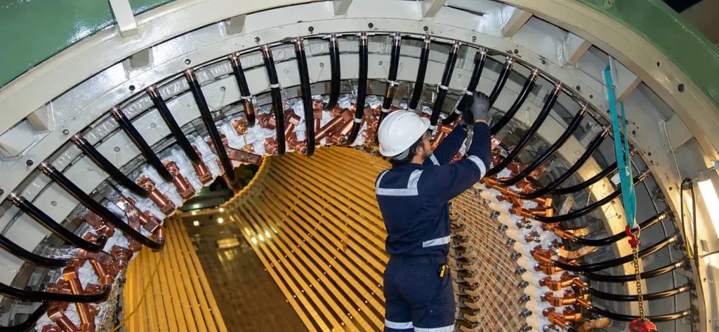
Stator visual inspections are one of the most important predictive maintenance activities for large utility generators. Performed with the rotor removed during major outages, these inspections allow direct examination of the core bore, slot wedges, winding surfaces, end-windings, and support structures. Unlike offline electrical testing that only quantifies existing damage, visual inspection reveals the root mechanical, electrical, and chemical causes — such as component looseness, corona activity, or hazardous contamination — before insulation breakdown or ground faults occur. A thorough visual inspection typically takes four to eight hours per end and frequently identifies repairable issues that avoid multimillion-dollar rewinds. This article provides a practical, in-depth guide to performing, documenting, and responding to stator visual inspections, with special emphasis on common degradation signatures and proven remedies.
Maintenance Procedures
Effective stator visual inspections follow a disciplined sequence:
- Safety and preparation — Complete lockout/tagout, verify a zero-energy state, and fully purge hydrogen (for hydrogen-cooled units). Provide bright, temporary LED lighting and use articulating borescopes for confined spaces.
- Core bore and vent duct inspection — Carefully examine the entire core bore and radial vent ducts for discoloration, fretting, or foreign material.
- Slot wedge assessment — Perform tap-testing or use automated wedge-mapping tools while visually checking for movement or gaps.
- Winding and end-winding examination — Inspect top and bottom bars, blocking, ties, and bracing, with special attention to slot exits, phase breaks, and areas prone to contamination.
- Support structure review — Evaluate keybars, belly bands, surge rings, and end-winding supports for signs of looseness or movement.
- Detailed photographic documentation — Capture high-resolution images with scale references and precise location tagging.
- Gentle cleaning — Vacuum loose debris or use low-pressure dry air; avoid solvents until the contamination type is confirmed.
Inspections should be conducted every four to six years or following any significant vibration or operational event. Robotic air-gap inspection systems can provide supplementary data between major outages.
IEEE & ANSI Guidance
Industry standards strongly endorse detailed visual inspection as an essential part of generator maintenance. ANSI/IEEE Std 67 (Guide for Operation and Maintenance of Turbine-Generators) explicitly states that proper maintenance requires combining electrical tests with thorough visual examinations of all accessible stator components. IEEE Std 56 (Guide for Insulation Maintenance of Large AC Rotating Machinery) and IEEE C50.13 (Standard for Cylindrical-Rotor Synchronous Generators) further emphasize that visual findings must guide repair decisions. EPRI guidelines on generator visual inspection reinforce the need to document and trend mechanical, electrical, and chemical degradation. Compliance with these standards helps meet NERC reliability requirements, supports insurance audits, and reduces operational risk. Ignoring visible signs of distress in favor of electrical test data alone can lead to preventable failures and increased liability.
Documentation
High-quality documentation turns a visual inspection into a powerful trending and decision-making tool. Use a standardized digital checklist that records:
- Exact component location (slot number, axial position, circumferential clock position)
- Defect description, severity rating, and annotated photographs
- Comparison with findings from previous outages
- Quantitative data such as wedge movement or clearance measurements
Store all records in a secure, searchable database linked to the generator serial number and outage date. Thorough documentation satisfies IEEE 67 requirements and provides essential evidence for root-cause analysis if problems escalate.
Place a Generex Technical Field Advisor on-site to oversee work, guide technicians, and protect your interests.
Need Maintenance Direction
and Support?
Common Issues and Remedies
Several recognizable visual indicators reveal mechanical looseness, electrical stress, or chemical contamination in large utility generators.
Greasing
Greasing appears as a sticky, yellowish-brown or black paste smeared across winding surfaces, blocking, slot wedges, connection rings, or support structures, with a consistency similar to peanut butter. Both peanut butter and generator greasing result from the same chemical-mechanical process: hydrogenated oil forming a thick paste. In peanut butter, vegetable oils are hydrogenated and mechanically whipped to create a spreadable solid; in the generator, turbine lube oil leaks past the seals into the hydrogen atmosphere, where hydrogen gas, oil, and the continuous mechanical agitation from 120 Hz vibration at loose components combine to produce the greasy paste. This material accumulates precisely where relative motion occurs — slot exits, end-winding ties, connection ring blocking, or axial support (“gunstock”) interfaces.
Greasing can accelerate insulation abrasion and trap conductive particles, eventually leading to surface tracking or ground faults.
Dusting
Dusting is a dry, fine white or light-colored powder that collects on surfaces in the complete absence of oil. It signals loose insulating or blocking components rubbing against each other or the core due to vibration. Without oil to bind the particles, the abraded mica or glass insulation simply forms a dry dust. If left unaddressed, dusting progresses to insulation thinning and bar migration.
Red Dusting
Red dusting is a more specific and serious variant typically found inside the stator core near the radial vent ducts. This distinctive reddish powder is frequently a symptom of loose keybars or belly bands. It results from core resonance modes — either at the fundamental natural frequency or a harmonic — that cause repeated micro-movement between the core laminations, keybars, and supporting belly bands. The red color typically comes from fretting wear on the steel components. Red dusting near vent ducts is a strong indicator of core looseness that can lead to lamination damage, increased vibration, and hot spots if not corrected. Early detection allows for targeted tightening or re-keying before major core damage occurs. Units with core resonance issues can sometimes be detected and quantified by means of an acoustic survey of the exterior of the generator during operation.
Corona Discharge
Corona discharge is a white, frosty-looking surface deposit often observed on air-cooled generators, and the affected areas can also exhibit what looks like localized burning. It commonly appears at the slot exit on high-voltage bars or coils, as well as at phase breaks in the end-windings where a high-voltage winding is adjacent to a low-voltage bar. In these locations, the local electric field is high enough to cause ionization of the surrounding air, producing corona discharge. The resulting ozone and nitrogen oxides chemically attack the insulation surface, creating the characteristic white, frost-like deposit and gradually eroding the insulation. Corona activity is particularly pronounced in air-cooled units because there is no pressurized hydrogen to suppress ionization. If unchecked, corona can lead to insulation degradation, tracking, and eventual ground or phase-to-phase faults.
Lead Carbonate Contamination
Lead carbonate contamination appears as a distinctive yellowish-white, chalky, or crusty powdery deposit, often resembling dried baking soda or fine white scale. It is most commonly encountered on stator windings, end-windings, core bore surfaces, or support structures in older generators. The root cause is the degradation of historical lead-based paints, anti-corrosion coatings, or certain sealants and gaskets originally applied during manufacture for rust prevention on steel components. Over decades of exposure to heat, moisture, carbon dioxide, and vibration, these lead compounds oxidize and carbonate, forming lead carbonate (PbCO₃). To confirm its presence, perform an on-site chemical spot test using a sodium rhodizonate swab (which turns pink or red in the presence of lead) or collect small samples for laboratory analysis via X-ray fluorescence (XRF) or inductively coupled plasma (ICP) spectroscopy. If it is encountered, stop work — immediate abatement is required because lead carbonate is a regulated hazardous material and is hazardous to health.
Abatement procedures include: (1) isolating the area with containment barriers; (2) using HEPA-filtered vacuums and wet-cleaning methods to suppress dust (never dry-sweep or use compressed air); (3) requiring workers to wear appropriate PPE (N95 or higher respirators, Tyvek suits, and gloves); and (4) disposing of all waste as hazardous material per OSHA 1910.1025 and EPA guidelines. Failure to follow proper abatement can create inhalation or ingestion risks and regulatory violations. Once abated, apply modern non-lead protective coatings and monitor for recurrence.
Remedies by Severity
Remedies depend on the severity of the finding:
- Light greasing or white dusting: Thorough cleaning, re-tightening of ties and blocks, and application of a compatible insulating varnish.
- Red dusting near vent ducts: Detailed inspection of keybars and belly bands, followed by re-tightening, shimming, or replacement of loose components.
- Corona discharge: Clean the affected areas, inspect for underlying insulation damage, apply semi-conductive coatings or grading paints to reduce electric-field stress, and consider installing corona-suppression systems if the problem is recurrent.
- Lead carbonate: Full hazardous-material abatement as described above, followed by thorough cleaning and reapplication of non-lead protective systems.
- Severe cases: May require localized coil repairs or a full stator rewind.
Repair Scenarios
Visual inspection findings directly determine the repair scope:
- Minor — Localized greasing, dusting, red dusting, light corona, or trace lead carbonate: cleaning, re-blocking, varnishing, or application of grading coatings plus targeted abatement (typically two to four days).
- Moderate — Widespread looseness with red dusting indicating keybar or belly band issues, significant corona damage, or confirmed lead carbonate: re-keying, belly band adjustments, enhanced core clamping, end-winding reinforcement, or full abatement (one to two weeks).
- Major — Extensive fretting, insulation abrasion from greasing or dusting, core resonance damage, advanced corona erosion, or heavy lead carbonate contamination: a full stator rewind combined with core repairs or restacking, plus comprehensive hazardous-material handling (6–12+ weeks).
All repairs must use materials compatible with the original Class F (or higher) insulation system and follow OEM design intent. Post-repair visual re-inspection plus electrical testing confirms the effectiveness of the work.
Summary & Conclusions
Stator visual inspections remain the most practical and cost-effective method for detecting early mechanical, electrical, and chemical degradation in large utility turbine-driven generators. By identifying greasing (the hydrogenated-oil paste formed by turbine oil, hydrogen, and vibration at loose points), ordinary dusting (dry fretting from loose insulation), red dusting near vent ducts (a key indicator of loose keybars or belly bands caused by core resonance modes), corona discharge (white, frosty deposits from high electric-field ionization in air-cooled units), and lead carbonate contamination (chalky white deposits from degraded historical lead-based coatings), maintenance teams can address root causes long before they result in forced outages or catastrophic failures. Strict adherence to ANSI/IEEE Std 67, IEEE 56, and related EPRI guidelines, combined with meticulous documentation and timely repairs, maximizes generator reliability and service life. For utilities and plant operators, investing in expert-led stator visual inspection programs during every major outage is a proven strategy to avoid multimillion-dollar losses and ensure continued safe, reliable operation.

About the Author
Charles J. Wolfe is the Founder and Principal Engineer of Generex Consulting, with over 30 years of global experience in power generation. He is a recognized expert in generator and excitation systems, trusted by clients worldwide for solving complex engineering challenges.