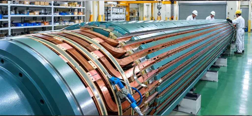
Generator Thermal Sensitivity Test | Rotor Vibration Diagnosis
Introduction
Vibration that increases proportionally with rising excitation (field) current is a classic symptom of thermal sensitivity in large utility generators. This condition occurs when localized heating in the rotor field winding causes differential thermal expansion, rotor bowing, and a resulting increase in 1× running-speed vibration at the bearings. The thermal sensitivity test is a targeted online diagnostic performed while the generator runs at constant speed and load. It systematically varies excitation current while monitoring vibration amplitude and phase to confirm that the vibration is thermally driven rather than mechanically or aerodynamically induced. Early detection through sound
vibration monitoring and analysis prevents progression to severe rotor bow, unbalanced magnetic pull, increased bearing loads, and potential forced outages.
Background
Thermal sensitivity has been documented in utility generators since the 1970s, particularly in high-speed two-pole rotors where centrifugal forces amplify even small thermal gradients. Original equipment manufacturers (OEMs) have repeatedly warned customers about this phenomenon and recommend performing thermal sensitivity testing whenever 1× vibration tracks excitation current. Ignoring the symptom can lead to catastrophic rotor bowing or winding failure.
Theory of Operation
The rotor field winding carries high DC current, ranging from hundreds to thousands of amps. Any inter-turn short or insulation degradation creates localized I²R heating. In a healthy rotor, heating is uniform and the rotor expands symmetrically. When a short develops, one pole or section heats more than the rest, causing asymmetric thermal expansion. The rotor bows toward the hotter side, shifting the mass centerline and producing a 1× centrifugal force vector that increases vibration amplitude at the bearings.
The vibration response is linear with field current because heating, and therefore bow, is proportional to I². Phase analysis often shows the high spot migrating toward the hotter pole. The test isolates thermal effects by holding speed and load constant while varying only the excitation current.
Test Procedure Overview
The test is performed online at constant synchronous speed and constant load, typically at minimum load or no-load for safety. The key steps are outlined below.
Preparation. Install or verify vibration transducers, using proximity probes at both bearings, preferably in both the X and Y directions. Ensure the generator is stable at operating speed, then record baseline vibration at minimum excitation.
Data acquisition setup. Use a multi-channel vibration analyzer with a phase reference (keyphasor). Log 1× and 2× vibration amplitude, phase, and field current.
Test execution. Hold speed and load constant and gradually increase excitation current in steps. At each step, allow time for thermal stabilization and record vibration data. Continue to rated or maximum safe field current, or until vibration limits are approached. Optionally, decrease excitation stepwise to check for hysteresis.
Safety. Monitor bearing temperatures, hydrogen pressure and purity, and vibration trip setpoints throughout. Do not exceed OEM vibration or temperature limits.
Place a Generex Technical Field Advisor on-site to oversee work, guide technicians, and protect your interests.
Need Maintenance Direction
and Support?
Interpreting the Results
The response of vibration amplitude and phase to changing field current reveals the rotor’s condition. The three characteristic outcomes are:
- Healthy rotor: vibration amplitude remains stable or changes only minimally.
- Marginal: a moderate increase with stable phase — monitor closely during the next outage.
- Thermal sensitivity confirmed: a clear, proportional increase in 1× vibration amplitude with rising field current, accompanied by a 180° phase shift or migration of the high spot. The 2× vibration usually remains unchanged.
Plot vibration amplitude and phase against field current. A linear upward slope in amplitude with consistent phase behavior confirms thermal sensitivity caused by rotor bow from uneven heating. Trending against prior tests is critical: a worsening slope indicates progressing shorts.
Repair Scenarios
If thermal sensitivity is confirmed, the recommended response depends on the severity of the measured slope and the number of poles affected:
- Minor cases (small slope, early-stage shorts): perform complementary rotor tests such as the pole drop test, RSO test, and flux probe test. If confirmed, schedule localized repair or varnish application during the next outage.
- Moderate cases (moderate slope, confirmed shorts on one pole): plan a pole-coil repair or partial rewind, then re-test after the repair.
- Severe cases (steep slope, multiple poles affected, vibration approaching trip limits): immediate rotor removal and a full rewind are required. A post-repair thermal sensitivity re-test is mandatory.
All repairs must be validated with a repeat thermal sensitivity test plus a full rotor diagnostic suite (RSO, flux probe, and AC impedance testing) before the unit is returned to service.
IEEE & ANSI Documentation
Thermal sensitivity testing is addressed in IEEE Std 115-2019, IEEE Guide for Test Procedures for Synchronous Machines, under rotor diagnostic methods for vibration and inter-turn faults. Supporting guidance appears in IEEE Std 56-2016, IEEE Guide for Insulation Maintenance of Electric Machines. OEM documentation provides specific warnings and test protocols. IEEE standards are frequently dual-designated as ANSI/IEEE and represent globally recognized best practice.
Summary & Conclusions
Thermal sensitivity testing is a straightforward yet powerful online diagnostic for large utility generators that exhibit vibration tracking rising excitation current. By holding speed and load constant while varying field current and monitoring the 1× vibration response, the test isolates rotor thermal bow caused by I²R heating in shorted turns. When vibration amplitude rises proportionally with field current, it confirms a rotor winding issue that DC or low-power tests often miss.
Performed and interpreted per IEEE 115 and supported by OEM documentation, the test enables early, targeted repairs that prevent vibration-induced damage, unbalanced magnetic pull, and costly forced outages. As generator fleets age and operate under higher cyclic duty, routine thermal sensitivity testing has become an indispensable part of modern predictive maintenance and condition monitoring programs, delivering high diagnostic value with minimal downtime and no rotor removal required.

About the Author
Charles J. Wolfe is the Founder and Principal Engineer of Generex Consulting, with over 30 years of global experience in power generation. He is a recognized expert in generator and excitation systems, trusted by clients worldwide for solving complex engineering challenges.