Recurrent Surge Oscillography (RSO) Test Explained
INTRODUCTION
The rotor (field) winding of a large utility generator is subject to severe mechanical, thermal, and electrical stresses that can cause inter-turn insulation failures. These shorts are often intermittent, voltage-dependent, or masked by contact resistance, making them difficult to detect with conventional DC tests such as Megger, Pole Drop, or AC Impedance.
The Recurrent Surge Oscillography (RSO) Test is a sensitive, high-frequency surge-wave diagnostic that injects fast-rising, high-frequency voltage pulses into the rotor winding and analyzes the reflected waveforms to locate turn-to-turn faults with high resolution. It is widely used during commissioning, major outages, post-repair verification, and root-cause investigations.
BACKGROUND
Inter-turn shorts in rotor windings have caused numerous forced outages since the 1950s. Traditional DC-based tests, as well as the AC Impedance test, often miss low-resistance or intermittent faults. The recurrent surge oscillography technique, developed in the 1970s and refined in the 1980s–1990s, applies traveling-wave principles previously used in cable-fault location.
It quickly became a standard utility practice because it can detect faults that other methods overlook. Today it is performed in conjunction with Pole Drop, AC Impedance, and Megger/P.I. tests as part of a complete rotor diagnostic program. For detecting and locating shorted rotor turns, the ultimate authority is the online flux probe test, which requires a special sensor to be installed permanently in the unit. This is handled in a separate article on this website.
THEORY OF OPERATION
The RSO test operates on the principle of Time Domain Reflectometry (TDR). The rotor winding is treated as a distributed-parameter transmission line with a characteristic impedance determined by its inductance and capacitance per unit length. A fast-rising voltage pulse is injected at one end of the winding. This pulse propagates along the winding at nearly the speed of light. At any point of impedance discontinuity — such as a turn-to-turn short — part of the pulse energy is reflected back toward the injection point. The reflection coefficient (gamma) at the fault is given by:
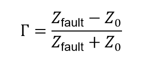
where
Z0 is the characteristic impedance of the healthy winding and
Zfault is the reduced impedance at the short.
A short produces a negative reflection (inverted pulse) that appears as a characteristic “notch,” “step,” or “distortion” on the oscillography trace. The location of the fault is precisely determined using time-of-flight computation: the time delay between the incident pulse and the reflected pulse is measured, and the distance to the fault is calculated as:
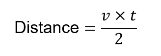
where (v) is the propagation velocity along the winding and (t) is the round-trip time. Because the test uses recurrent (repetitive) surges, the oscillography displays a stable, superimposed trace for easy visual comparison. The high-frequency nature of the surge makes the test highly sensitive to even single-turn shorts.
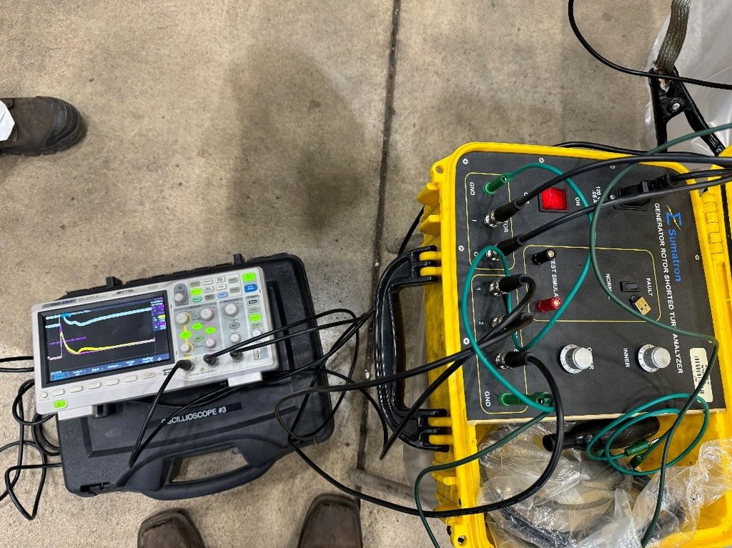
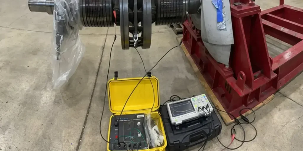
RSO Test Set in Use
TEST PROCEDURE
The RSO test is flexible and can be performed in two configurations:
- Offline (most common): With the rotor stationary (in place or removed).
- Online at full speed, no-load conditions: Possible when collector rings / slip rings are accessible (i.e., the unit is not configured with a brushless exciter). In this mode, the test is conducted while the generator is running at synchronous speed but not connected to the grid and with zero field current. Temporary connections are made to the slip rings to inject the surge pulses while the rotor is spinning.
Offline Procedure (Standard)
- Disconnect and isolate the rotor field leads. Ground the shaft.
- Connect the recurrent surge oscillography instrument to one field terminal.
- Apply recurrent surges (100–500 V peak, 50–200 ns rise time) and record waveforms from each pole or coil group.
- Compare traces against a healthy reference or the opposite pole.
- Document any distortions and their time-of-flight.
Online Procedure (When Slip Rings Are Accessible)
The same surge injection and waveform analysis is used, but is performed while the rotor is spinning at rated speed with no excitation applied. This can provide additional insight into faults that may only appear under centrifugal force. The complete test typically takes 1–2 hours.
INTERPRETING RESULTS
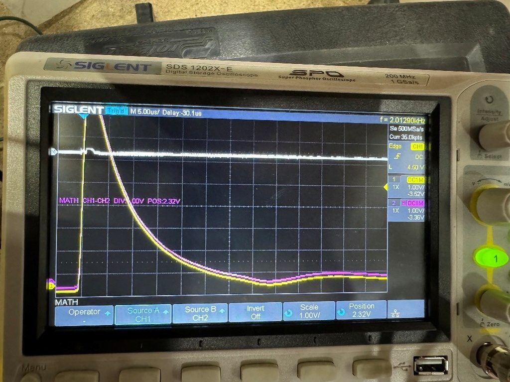
- Healthy Rotor: Waveforms from all poles are smooth, identical in shape, and superimpose perfectly with no visible notches or steps.
- Marginal: Small, repeatable distortions that do not grow with repeated pulsing.
- Faulty: Clear “notch,” “step,” or inversion in the waveform at a specific time delay, indicating a turn-to-turn short. The earlier the anomaly appears (shorter time-of-flight), the closer the fault is to the injection point.
Results are often expressed as “good,” “suspect,” or “failed” per pole, with fault location estimated as a number of turns or a percentage of pole length. Trending is essential—new or worsening distortions on successive tests confirm progressive degradation.
Our engineers identify the true root cause of equipment failures, and help prevent future events
Why Did Your Unit
Suddenly Trip?
REPAIR SCENARIOS
If results indicate faults:
- Minor Shorts (single-turn fault near end of pole): Inspect accessible areas, clean contamination, or apply insulating varnish. Re-test after repair.
- Moderate Shorts (clear notch, several turns affected): Locate the exact coil using further subdivision testing, then repair or replace the affected coil/turns.
- Severe/Widespread Shorts (multiple poles affected or large waveform distortion): Full rotor rewind or complete pole-coil replacement is usually required.
All repairs must be followed by a repeat RSO Test (plus 500 V Megger/P.I., Pole Drop, and AC Impedance tests) to confirm the fault has been eliminated before the rotor is returned to service.
IEEE & ANSI DOCUMENTATION
The recurrent surge oscillography (RSO) test method is described in IEEE Std 115-2019, IEEE Guide for Test Procedures for Synchronous Machines, under rotor inter-turn fault detection techniques. Supporting guidance appears in IEEE Std 56-2016, IEEE Guide for Insulation Maintenance of Electric Machines. While no standalone ANSI/IEEE standard is dedicated exclusively to the RSO test, IEEE 115 is the primary reference and is frequently dual-designated as ANSI/IEEE. OEM technical information letters and EPRI reports provide machine-specific procedures and acceptance criteria.
SUMMARY & CONCLUSIONS
The Recurrent Surge Oscillography (RSO) Test is a highly sensitive, high-frequency surge-wave diagnostic that detects turn-to-turn shorts in large utility generator rotors by applying Time Domain Reflectometry (TDR) principles. Fast-rising pulses are injected into the winding, and reflections caused by impedance discontinuities (shorts) are analyzed using time-of-flight computation to locate faults precisely. The test can be performed offline with the rotor stationary or online at full speed under no-load conditions when collector rings / slip rings are accessible (i.e., the unit is not equipped with a brushless exciter). When performed and interpreted according to IEEE 115, the RSO test reveals faults that DC or low-frequency AC tests often miss, enabling targeted repairs that prevent vibration, unbalanced magnetic pull, loss of excitation, and costly rotor rewinds. As generator fleets age and operate under higher cyclic duty, routine RSO testing has become an essential part of modern predictive maintenance programs, delivering precise fault location with minimal equipment and downtime.

About the Author
Charles J. Wolfe is the Founder and Principal Engineer of Generex Consulting, with over 30 years of global experience in power generation. He is a recognized expert in generator and excitation systems, trusted by clients worldwide for solving complex engineering challenges.