Generator Stator RTD Testing: Function & 500V Megger Test
Introduction
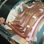
A Resistance Temperature Detector (RTD) is a precise temperature sensor that works by measuring the change in electrical resistance of a metal element as temperature changes. In large generators, RTDs are embedded directly in the stator winding slots (usually between the top and bottom coils), as well as in the hot and cold cooling gas paths, to provide accurate, real-time monitoring of stator component temperatures.
Because stator winding temperature is one of the most critical parameters affecting generator life, reliable RTD performance is essential. This guide walks through the two tests every stator RTD must pass during a planned outage: the function test and the 500 VDC Megger test.
Purpose of Stator RTDs
- Protect the generator from overheating by feeding data to protective relays.
- Allow operators to monitor hot-spot temperatures and stay within the generator’s capability curve.
- Give the control room and operations staff insight into how effectively the air or hydrogen coolers are functioning by comparing gas cooler inlet and outlet temperatures. Trending this data helps operators catch generator cooling issues before they escalate.
- Provide trending data for insulation aging and maintenance planning.
Types of RTDs Used in Generators
Stator RTDs come in a few common variants. The choice of sensing element, wiring configuration, and element count depends on the machine vintage, the OEM, and how the RTD data feeds into protection and monitoring. The sections below cover the main types you will encounter on large generators.
Copper RTDs (Cu10 or Cu100)
These use copper wire as the sensing element. They offer excellent linearity and thermal matching to the copper stator winding. Copper RTDs are commonly found in older Westinghouse and some GE machines. They are chosen when precise correlation with the actual winding temperature is prioritized. Copper RTDs come in both 10 Ohm and 100 Ohm nominal resistance at 25 °C.
Platinum RTDs (Pt100)
Platinum RTDs are the modern standard. They provide higher accuracy (±0.3 °C or better), superior long-term stability, and better resistance to vibration and contamination. Most newer generators from Siemens, GE, and Mitsubishi use Pt100 RTDs for critical protection and condition monitoring. Pt100 RTDs come in 100 Ohm nominal resistance at 25 °C.
3-Wire RTD Configuration and Lead Wire Compensation
Long cable runs from the RTD in the stator slot to the terminal box add significant lead resistance, which can cause measurement errors. A 3-wire RTD solves this by using three leads:
- Two wires carry the measurement current.
- The third wire senses the voltage directly across the RTD.
The measuring instrument calculates and subtracts the lead resistance, leaving only the true RTD resistance. This compensation is essential for accurate readings over the long and varying distances typical in generators.
Dual-Element RTDs
Many generators use dual-element RTDs, which contain two independent sensing elements inside a single probe. The main reasons for using dual-element RTDs are:
- Redundancy — if one element fails, the second continues to provide data.
- Voting logic — relays can compare both elements and alarm on discrepancies.
- Separation of duties — one element for monitoring, the second dedicated to protection relays.
Testing Stator RTDs
Each element must be tested individually during outages. Two tests are performed on every stator RTD:
- RTD Function Test — verifies that the RTD accurately measures temperature using an Ohm-meter or precision calibrator.
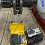
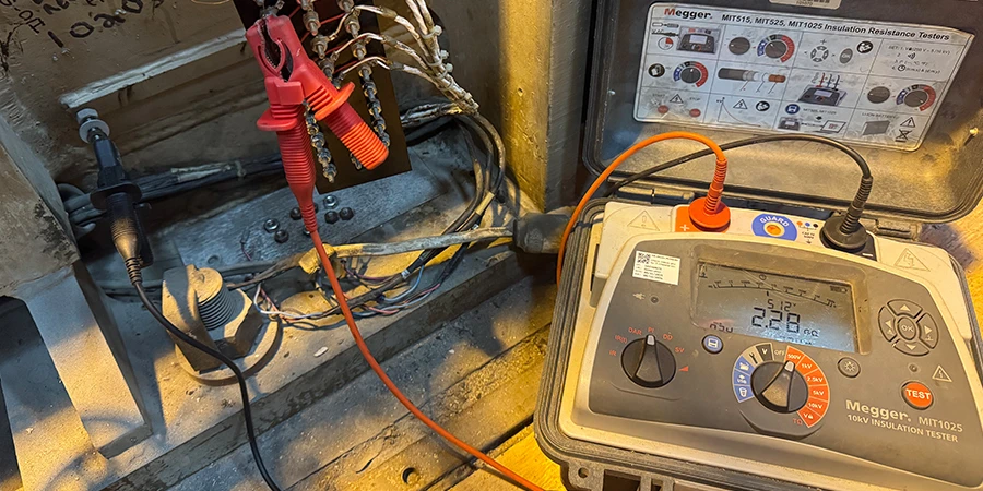
- RTD Megger Test at 500 VDC — verifies the insulation integrity between the RTD sensor/leads and ground (stator core) using a 500 V insulation tester with a one-minute hold time.
Testing Methodology
Both tests are performed with the generator offline and every RTD lead landed at the terminal box disconnected. The function test is performed first to confirm the sensor still reads accurately, followed by the Megger test to confirm the RTD and its leads are still well insulated from ground. Work through every element on every probe in the same order so the results are easy to compare against past outages.
Prerequisites: Generator shut down and locked out. All RTD leads disconnected at the terminal box.
RTD Function Test Procedure
- Connect a precision RTD calibrator or Ohmmeter to each RTD element.
- Read the resistance from lead A to B, from B to C, and from C to A.
- Simulate several temperatures (typically 0 °C, 50 °C, 100 °C, and 150 °C).
- Using the resistivity formula for copper or platinum (as applicable), compute the indicated temperature.
- Using a handheld thermometer, compare the indicated temperature to the measured temperature and note any significant discrepancy.
- Verify that the control system or protective relay reads within ±1–2 °C of the simulated value.
RTD Megger Test Procedure (500 VDC)
- Short the three leads of each RTD element together.
- Apply 500 VDC between the shorted leads and stator ground.
- Hold for one minute.
- Measure and record the insulation resistance.
- Repeat for every RTD and every element on dual-element probes.
The 500 VDC Megger test on stator RTDs uses the same insulation-testing principles covered in our broader guide to the Megger polarization index test.
Interpreting the Results
The raw numbers from either test only mean something once you compare them to accepted acceptance criteria and to the same RTD’s history. The thresholds below reflect common industry practice for stator RTDs and align with IEEE Std 43 guidance for insulation resistance. Always cross-check against your OEM manual, since a few manufacturers publish tighter or looser limits.
Function Test Results
- Good: ±1–2 °C accuracy.
- Marginal: ±3–5 °C error.
- Failed: greater than 5 °C error, or open circuit.
Megger Test Results (500 VDC)
| Insulation Resistance | Interpretation | Action Required |
| > 100 MΩ | Excellent | None |
| 10 MΩ – 100 MΩ | Acceptable | Monitor |
| 1 MΩ – 10 MΩ | Marginal | Investigate |
| < 1 MΩ | Failed (shorted to ground) | Replace RTD immediately |
What to Do if Results Are Bad
A bad reading is not automatically a failed RTD. Wiring, terminal connections, moisture, and lead contamination cause a large share of first-pass failures, and all of them are correctable in the field. Work through the easy causes first, retest, and only condemn the sensor once the surrounding wiring and terminations have been ruled out.
Failed Function Test
- Check the wiring first.
- Verify that connections are tight.
- If the connections are rusted or corroded, clean them, reconnect, and re-test.
- Replace the defective RTD element or the entire dual-element RTD.
Failed Megger Test
- Clean and dry the leads, then retest.
- If resistance remains low, replace the RTD. This typically requires removing the slot wedge and top coil in that location.
- After replacement, re-perform both the function test and the 500 VDC Megger test.
- If the RTD cannot be removed, take it out of service by connecting all three leads together, grounding them, and setting them aside. A follow-up partial discharge test on the stator is often prudent when RTD insulation failures are found, to rule out broader winding insulation degradation.
Need Maintenance Direction
and Support?
Place a Generex Technical Field Advisor on-site to oversee work, guide technicians, and protect your interests.
RTDs Versus Thermocouples
Generators use both RTDs and thermocouples, but for different jobs. Understanding the trade-off between the two helps operators know which sensor is doing what on their machine, and why a failed RTD cannot simply be swapped for a spare thermocouple. The comparison below covers the working principle, accuracy, and typical applications of each.
RTDs
- Work on the principle of resistance change with temperature.
- Offer high accuracy (±0.3 °C) and excellent stability.
- Used primarily for stator winding temperature monitoring (embedded in slots) and core temperature monitoring.
- Preferred when precision and long-term reliability are critical.
Thermocouples
- Work on the principle of voltage generation at the junction of two dissimilar metals (Seebeck effect).
- Less accurate (±1–2 °C or more) and more prone to drift, but very fast responding and rugged.
- Used mainly for bearing temperature monitoring, lube oil temperatures, hydrogen cooler outlet temperatures, and some exciter components.
- Chosen where fast response or high-temperature capability is needed and extreme precision is less critical.
Controlling Standards and Documentation
- IEEE Std 43 — Recommended Practice for Testing Insulation Resistance of Electric Machinery (covers RTD insulation resistance testing).
- IEEE Std 115 — Test Procedures for Synchronous Machines.
- ANSI/NETA MTS — Maintenance Testing Specifications for Electrical Power Equipment.
These tests are also required by most OEM maintenance manuals.
Stator RTD testing is typically scheduled alongside other outage work such as Westinghouse stator bolt checks and DC insulation testing. For high-voltage stator winding integrity, the DC leakage and DC hipot test provides a complementary check of the main insulation system.
Summary and Conclusions
RTDs are used for critical, high-accuracy stator winding and core temperature measurement. Thermocouples are used where speed of response and ruggedness are more important, such as bearings and auxiliary systems. RTDs are vital sensors for safe and efficient generator operation. The function test ensures they provide accurate temperature data, while the 500 VDC Megger test ensures they remain safely insulated from the high-voltage stator environment. Regular testing of stator RTDs helps prevent false trips, missed protection, and undetected hot spots.

About the Author
Charles J. Wolfe is the Founder and Principal Engineer of Generex Consulting, with over 30 years of global experience in power generation. He is a recognized expert in generator and excitation systems, trusted by clients worldwide for solving complex engineering challenges.