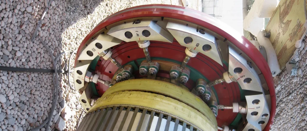
Brushless Exciter Testing on Large Utility Generators
Introduction
Brushless exciters are the standard excitation system on modern large utility generators. They convert a low-level DC control signal from the Automatic Voltage Regulator (AVR) into the high-power DC field current required by the main generator rotor. Unlike brushed systems, brushless exciters eliminate slip rings and carbon brushes, which reduces maintenance and contamination while improving reliability. Comprehensive brushless exciter testing is essential during commissioning, major outages, and post-repair verification, and whenever symptoms such as abnormal field current, vibration, excitation instability, or loss-of-field alarms appear. This procedure is a guide to testing, inspecting, overhauling, and troubleshooting common brushless exciters (for example, GE, Kato, Alstom, and Electric Machinery).
Background
Brushless exciters were introduced in the 1960s to overcome the limitations of brushed excitation systems. They have become the dominant design on generators rated above 100 MW. The exciter itself is a complete rotating synchronous machine mounted on the same shaft as the main generator. Common failure modes include diode failures on the rotating diode wheel, snubber degradation, PMG winding issues, insulation breakdown in the rotating armature or stationary field, and field ground detector malfunctions. Routine testing is critical because these components operate under high centrifugal forces and must deliver stable excitation under all conditions.
Theory of Operation
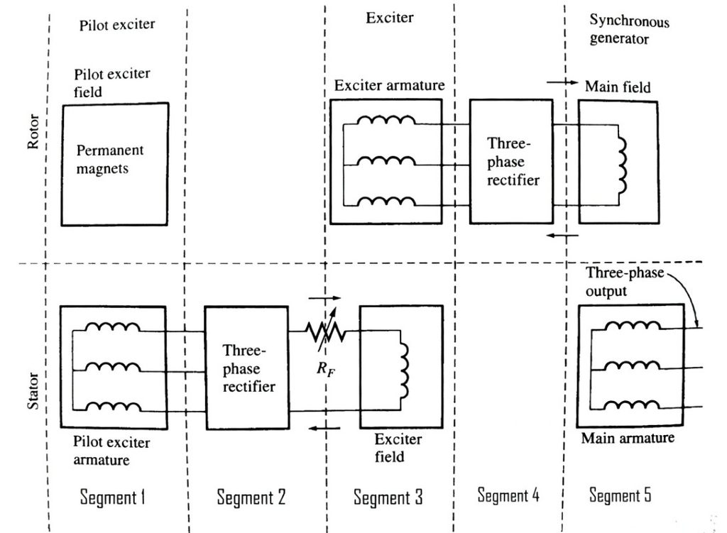
A brushless exciter functions as an electromechanical amplifier. It takes a low-level DC signal from the AVR (0 to 10 A, 0 to 20 V range) and produces a variable, high-power DC output (100 to 1,000 V, 50 to 5,000 A range) that is fed directly to the main generator rotor field winding. The system consists of up to four functional segments (see the figures in this article):
- Permanent Magnet Generator (PMG), which is optional
- Rotating armature
- Stationary field
- Diode wheel
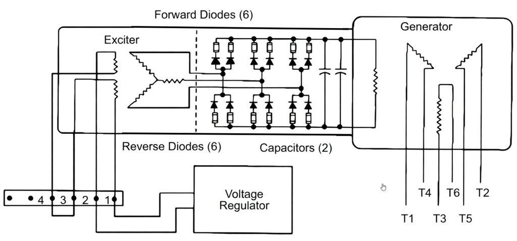
In units equipped with a PMG, the PMG supplies AC power to the stationary field poles. This creates a rotating magnetic field that induces AC voltage in the rotating armature. The diode wheel rectifies the AC to produce DC for the main generator field. Units without a PMG receive their exciter field signal directly from the AVR. The armature is typically a three-phase generator operating at 200 to 420 Hz and connected in a wye configuration.
Brushless Exciter Test Procedure
Perform testing offline with the rotor stationary. The generator must be fully isolated (52-G and 52-L locked out, and hydrogen systems purged if applicable), and all control power to the exciter and AVR must be disconnected. Complete a full walkdown before starting work.
Safety Considerations
- Verify stator isolation and grounding.
- Confirm that control power and AVR signals are locked out and tagged out.
- Ground the rotor forging for safety and improved test accuracy.
- Use proper PPE and follow lockout/tagout procedures.
Component Testing
- Permanent Magnet Generator (PMG, if equipped)
- Perform insulation resistance and polarization index (P.I.) testing on the PMG stator and rotor windings at 500 V DC.
- Measure the AC output voltage during a rated-speed or low-speed spin test.
- Check the PMG rectifier (if present) for proper diode forward and reverse resistance.
- Verify a balanced, undistorted output waveform with an oscilloscope.
- Caution: PMG magnets are extremely powerful. Keep metallic objects, credit cards, watches, and personnel with implants clear. Use a hoist for removal, and wrap the magnets to prevent them from attracting debris.
- Rotating Diode Wheel (including fuses, diodes, and RC snubber networks)
- Visually inspect for overheating, loose connections, discoloration, and mechanical damage. Match-mark all components before removal.
- Test each diode in diode-check mode (forward drop of approximately 0.5 to 0.7 V and infinite reverse resistance). Use optional DC or AC test setups (battery, resistor, ammeter, and voltmeter, or a neon-lamp circuit) to confirm function.
- Check each fuse for continuity and resistance using a digital low-resistance ohmmeter (DLRO). Replace the entire set if any fuse deviates by more than ±5% from the average.
- Test the RC snubber networks for correct resistance and capacitance.
- Perform a 500 V DC insulation resistance test on the diode wheel assembly.
- Stationary Field Poles
- Perform 500 V DC insulation resistance and P.I. testing on the stationary field winding.
- Conduct pole-drop testing: apply a convenient AC voltage (a multiple of the number of poles, such as 80 to 140 V) across F1 and F2, and measure the voltage drop across each pole with insulated probes. All drops should be within approximately 2% of the average and should sum to the applied voltage.
- Optionally, perform an AC impedance test: ramp the voltage in 5 to 10 V steps and plot impedance versus voltage for linearity. Non-linear behavior or bumps indicate shorted turns.
- Inspect the poles, core, wiring, and insulation for overheating, damage, and contamination.
- Rotating Armature
- Perform 500 V DC insulation resistance and P.I. testing. One test covers all phases because they are connected together.
- Measure the AC voltage output at the diode-wheel input terminals during a low-speed spin test.
- Check phase balance and confirm the absence of shorts.
- Inspect for cleanliness, banding cracks, overheating, and mechanical damage.
- Field Ground Detector
- Simulate a ground fault with a test resistor and verify that the alarm or trip occurs at the correct threshold (typically 5 to 100 kΩ).
- Test the insulation resistance of the detector wiring and components.
- For infrared or RF types, clean the lenses, LEDs, and phototransistors, and verify alignment between the transmitter (TX) and receiver (RX).
- Common causes of false alarms include dirty optics, poor connections, mechanical damage, and misalignment.
Need Maintenance Direction
and Support?
Place a Generex Technical Field Advisor on-site to oversee work, guide technicians, and protect your interests.
Interpreting Brushless Exciter Test Results
- Acceptable: Insulation resistance above 1 MΩ (corrected to 40 °C); P.I. above 1.5 (rotating components) or above 2.0 (PMG and stationary field); balanced voltages and currents; correct diode, fuse, and snubber readings; and reliable ground-detector operation.
- Marginal: Insulation resistance of 0.5 to 1 MΩ, slight unbalance, or marginal diode performance. Schedule monitoring or a re-test.
- Unacceptable: Low insulation resistance (below 0.5 MΩ), failed diodes, fuses, or snubbers, open or shorted windings, distorted waveforms, or a non-functional ground detector.
Brushless Exciter Repair Scenarios
- Minor issues (single diode, fuse, or snubber failure; marginal insulation): Replace the individual components, clean, and re-varnish the windings. Re-test the affected section.
- Moderate issues (multiple diodes or one degraded winding section): Replace the diode wheel assembly or rewind the affected armature or field section. Repeat the full test suite.
- Severe issues (widespread failures, low insulation on multiple components, or ground-detector malfunction): Perform a complete brushless exciter overhaul or replacement.
All repairs require a full repeat of the brushless exciter test suite before the unit returns to service.
IEEE and ANSI Documentation
Brushless exciter testing is covered in IEEE Std 115-2019, IEEE Guide for Test Procedures for Synchronous Machines, which includes procedures for rotating exciters and component verification. Additional guidance appears in IEEE Std 56-2016, IEEE Guide for Insulation Maintenance of Electric Machines. IEEE standards are frequently dual-designated as ANSI/IEEE and represent globally recognized best practice. OEM technical information letters provide machine-specific acceptance criteria and test voltages.
Summary and Conclusions
Brushless exciter testing is a comprehensive suite of diagnostics that verifies the health of every component in the excitation system of large utility generators equipped with rotating exciters. By systematically testing the PMG (if equipped), rotating diode wheel (diodes, fuses, and RC snubbers), stationary field poles, rotating armature, and field ground detector, along with visual inspection, cleaning, and functional checks, utilities can detect degradation before it causes loss of excitation or forced outages. When performed according to IEEE 115 and IEEE 56, the tests enable proactive repairs that maintain reliability and extend equipment life. As generator fleets age and operate under increasing cyclic duty, routine brushless exciter testing has become an indispensable part of modern predictive maintenance programs, delivering high value with minimal downtime.

About the Author
Charles J. Wolfe is the Founder and Principal Engineer of Generex Consulting, with over 30 years of global experience in power generation. He is a recognized expert in generator and excitation systems, trusted by clients worldwide for solving complex engineering challenges.