Stator Winding Transposition Test Guide
Introduction
The stator winding transposition test (also called the stator winding group transposition test) is an important diagnostic check used on large utility generators, particularly those with complex stator bar designs. It is especially relevant for older hydrogen inner-cooled machines that use external strand transposition rather than internal Roebel transposition.
Theory of the Test
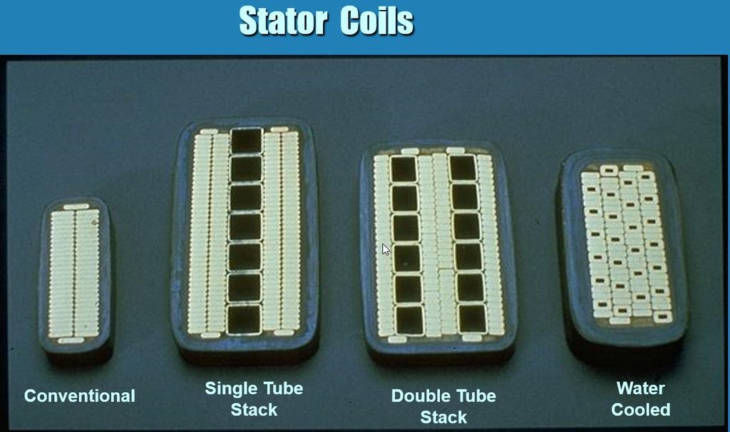
Large generators use Roebel bars (or transposed bars) in the stator winding. Each bar contains dozens of thin copper strands (sometimes hollow for direct cooling). These strands are deliberately transposed (twisted or crossed over in a specific pattern — typically 360° or 540° in the slot section) so that every strand spends equal time in the top and bottom of the slot. This transposition cancels out the unequal magnetic flux each strand sees: as you get further away from the rotor, the magnetic flux density decreases.
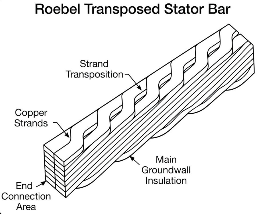
On a hydrogen inner-cooled winding, the slot portion has strands that do not have a Roebel transposition—they go straight through the slot always at the same radial position. In lieu of the internal Roebel, the strands are externally transposed by exactly one position per series connection. By the time you have completed the path from one end of the phase circuit to the other, the winding has undergone a full 360- or 540-degree rotation.
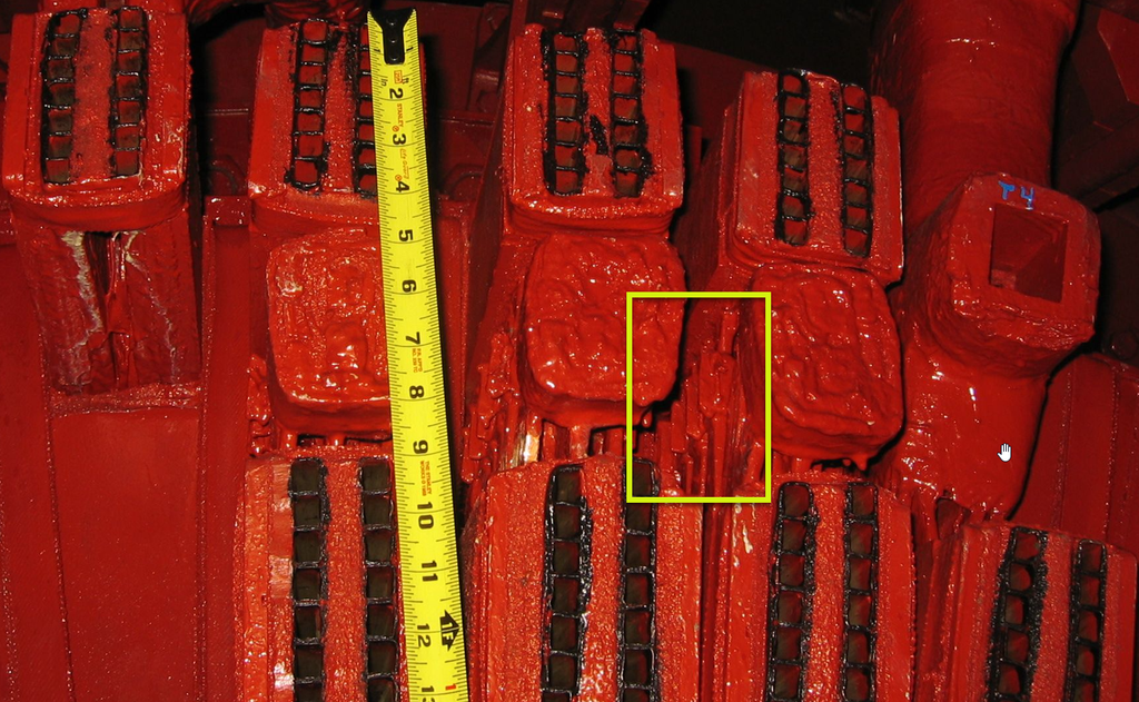
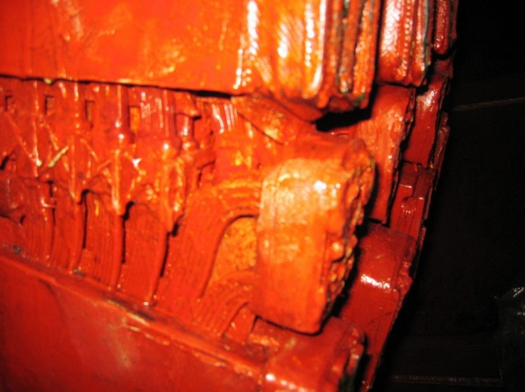
This design mitigates potentially huge circulating currents that would otherwise overheat the bar and waste efficiency. The transposition test simply checks whether that clever twisting is still working properly. It detects:
- Broken strands
- High-resistance connections (bad brazed joints)
- Failed strand-to-strand insulation (shorts between strands)
If the transposition is damaged, circulating currents spike, hotspots form, and the bar can fail catastrophically.
Why Westinghouse Generators Specifically?
Westinghouse (and later MHI) inner-cooled generators are famous for their complex non-Roebel bar designs with hollow cooling tubes. Service bulletins and repair specs from Westinghouse/Siemens explicitly call out transposition testing as a required check during outages, often alongside:
- Tube-to-tube resistance tests (checks cooling water paths)
- Tube-to-copper resistance tests (checks electrical continuity of the hollow strands)
It’s a go-to test for these legacy machines because strand failures were a known issue in some older inner-cooled winding designs.
Motivation for the Test
Imagine each bar as a bundle of 40–60 tiny wires (strands). Because of the magnetic field in the slot, the strands near the top see a slightly different flux than those near the bottom. Without transposition, the top strands would have higher induced voltage than the bottom ones → big circulating currents inside the bar. Proper Roebel transposition makes every strand “see” the exact same average flux over the length of the core. Induced voltages cancel out → almost zero circulating current. The test forces a small current through the bar and measures voltage drops or induced voltages across different strand groups. Any imbalance tells you a strand is broken, open, or shorted to its neighbor.
Performing the Test
When? During a major outage, after the generator is shut down, locked out, and the rotor is removed or at least the end bells are off. The winding must be completely isolated.
Procedural Overview
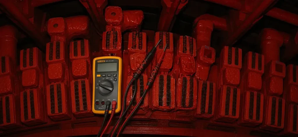
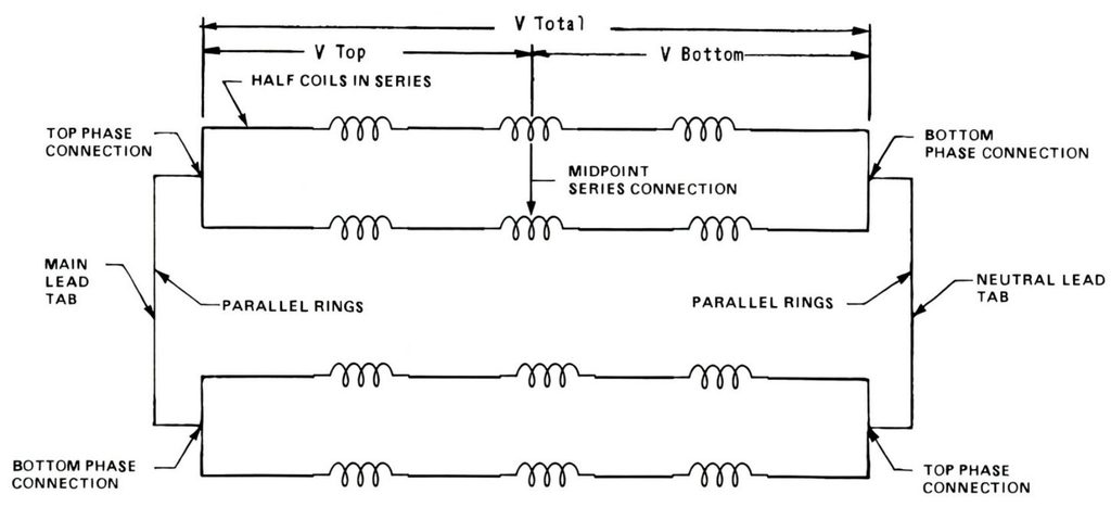
This procedure describes the method for verifying the electrical continuity, resistance balance, and transposition pattern of individual strands within isophase bus bars. The test is performed by applying a low-voltage AC supply or controlled DC current through an isolated parallel path between the neutral and line bushings, then measuring the voltage drop across individual strands or selected transposition points using a microvoltmeter. The recorded readings are compared to identify irregularities, strand imbalance, or possible defects in the transposition arrangement.
- Safety & Prep
- Verify zero energy (Megger/PI already passed).
- Disconnect all phase and neutral connections from the isophase buses.
- Identify the Bar Groups
- Each phase has multiple parallel paths (often 2–4 per phase).
- Focus on one parallel path at a time.
- Find which series connection is the electrical mid-point between line & neutral bushings.
- Apply Low-Voltage Source
- Use a low AC voltage or a DC current source.
- Inject the test current into one neutral bushing and out the line bushing, e.g. in on T4 and out on T1.
- Measure at the Other End
- Using a microvoltmeter, measure voltage drop across each individual strand or small groups of strands at the opposite end of the bar.
- Or measure between specific transposition points if accessible.
- Compare Readings
- In a healthy transposed bar, all strand-to-strand voltage drops (or resistances) should be nearly identical. The microvolt drop readings should plot as a clean sine wave as a function of transposition group number.
- Record the pattern for every bar in the parallel path.
- Repeat for All Three Phases
Need Maintenance Direction
and Support?
Place a Generex Technical Field Advisor on-site to oversee work, guide technicians, and protect your interests.
Interpreting Results
Compare readings across strand groups in each parallel path. In a properly transposed winding, voltage drops or resistances should be nearly uniform.
| Result Pattern | What It Means | Action Needed? |
| All strand voltages within 1–2 % | Healthy transposition — everything balanced | None — good to go |
| One or two strands show 0 V (open) | Broken strand or open brazed joint | Repair or bar replacement |
| One strand shows much higher voltage | That strand is not carrying current (open) | Investigate & repair |
| Strands show large imbalance | Failed strand insulation or short between strands | Further investigation (ELCID + visual) |
| Entire group shows high resistance | Bad connection at the clip or end winding | Re-braze or replace |
Trending is key — compare to previous outage data. Even a small increase in imbalance can signal early strand fatigue.
Controlling Standards and Documentation
- IEEE Std 62.2 (Guide for Diagnostic Field Testing of Electric Power Apparatus — Electrical Machinery) — Section 7.1.15 specifically describes the “stator winding group transposition test” and its use to locate broken strands or high-resistance connections.
- Inner-cooled generator service manuals: These often require the test on every major outage for their hydrogen inner-cooled designs.
Summary and Conclusions
Bottom line: The stator winding transposition test is your early-warning system for hidden strand problems inside non-Roebel, inner-cooled coils. It’s quick, non-destructive, and catches issues that Megger, Hipot, or ELCID might miss — especially on older Westinghouse inner-cooled machines. If a bar fails the test, you usually find it early enough to repair (re-braze or replace just that bar) instead of facing a forced outage from a melted bar later.

About the Author
Charles J. Wolfe is the Founder and Principal Engineer of Generex Consulting, with over 30 years of global experience in power generation. He is a recognized expert in generator and excitation systems, trusted by clients worldwide for solving complex engineering challenges.